background image

EPSILON CLOCK MODEL EC1S 


Spectracom Corporation 


EPSILON CLOCK User’s Manual 

5-6 


5.5

5.5

5.5

5.5


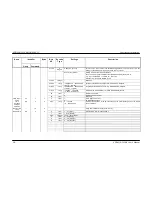
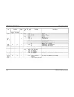
Command or query syntax

Command or query syntax

Command or query syntax

Command or query syntax    

Designation 

Command 

ID 

query ID  

Number of 

bytes  

Command 

validity conditions 

TOD output setup 

65 

(1) 

Status 

--- 

80 

37 

(1) 

Emission period of the time message on the 

TOD interface and on the remote control 

interface 

66 


Reset 

16 

--- 

(1) 

 GPS Date init 

68 

(1) 

Local Time 

71 

(1) et (3) 

Phase Correction  

72 

(1) et (3) 

Leap Second 

73 

(1) et (4) 

GPS Positioning 

10 

74 

19 

(1) et (3) 

Display 

13 

77 

(1) 

Alarm limits 

14 

78 

10 

(1) 

Version 

--- 

67 

10 

(1) 

Forced holdover mode  

15 

79 

(1) 

Manual time setting 

17 

81 

(1) et (5) 

Manual correction 

±

1s 

21 

85 

(1) et (5) 

Remote control mode 

18 

82 

(2) 


(1): Command authorized if the clock is in remote control mode. 
(2): Command always authorized. 
(3): Command authorized if the clock is not in forced holdover mode. 
(4): Command authorized if the current time reference is UTC. 
(5): Command authorized if the clock is in forced holdover mode. 
 
The tables that follow contain the format of the commands and the requests. 

Summary of Contents for EPSILON EC1S

Page 1: ...l Drive Rochester NY 14623 Phone US 1 585 321 5800 Fax US 1 585 321 5219 3 Avenue du Canada 91974 Les Ulis France Phone 33 0 1 64 53 39 80 Fax 33 0 1 64 53 39 81 www spectracomcorp com www spectracom...
Page 2: ...Corporation Specifications subject to change or improvement without notice Spectracom EPSILON CLOCK NetClock Ageless TimeGuard TimeBurst TimeTap LineTap MultiTap VersaTap and Legally Traceable Time ar...

Page 3: ...pectracom of the claim with full information as to the claimed defect Spectracom products shall not be returned unless a return authorization number is issued by Spectracom Spectracom products must be...

Page 4: ......

Page 5: ...Characteristics 2 4 2 5 Interface connector 2 4 2 6 Starting the Clock 2 5 2 7 Turning Off the Clock 2 6 3 FEATURES 3 1 3 1 Frequency Output 3 1 3 2 1PPS Output 3 2 3 3 Remote Control Interface RS232C...

Page 6: ...Display 5 4 5 3 11 Alarms limits 5 4 5 4 Time distribution on the remote control interface 5 5 5 5 Command or query syntax 5 6 6 FLAT ANGLE BRACKETS 6 1 6 1 Front of the Cabinet 6 1 6 2 Inside the Ca...

Page 7: ...rthermore learning from its behavior in different situations effects attributed to aging and to temperature variations while the GPS reference signal is present the frequency driver improves on the ac...

Page 8: ...tandard Features Standard Features The EPSILON CLOCK MODEL EC1S is used to generate maintain and provide the following A synchronized UTC GPS time reference The clock distributes a 1PPS signal a Time...

Page 9: ...ling your Spectracom product please verify that all material ordered has been received If there is a discrepancy please contact Spectracom Customer Service Customer service is available by telephone a...

Page 10: ...SSU Synchronization Supply Unit TRAIM Time Receiver Autonomous Integrity Monitoring UTC Universal Time Coordinated 1PPS One Pulse Per Second 1 PPS Driver Pulse signal obtained through division of the...

Page 11: ...sions in mm Mechanical Characteristics Dimensions in mm Mechanical Characteristics Dimensions in mm Front side MADEINFRANCEBYTEKELECSYSTEM J1 1PPS 10MHz POWER GPSANTENNA status lock EPSILON CLOCK Seri...

Page 12: ......

Page 13: ...ximum operating ambient temperature does not exceed 70 C 2 2 2 2 2 2 2 2 Preliminary Connections Preliminary Connections Preliminary Connections Preliminary Connections Before starting the EPSILON CLO...

Page 14: ...king an earth conductor WARNING If the protective conductor s path to ground is broken or defeated the danger of electrical shock to the operator may be present Before disconnecting the unit from the...

Page 15: ...n AMP mini mate n loc female connector AMP part number 172329 1 with crimp pin 22 18 AWG AMP part number 170364 1 Pin out 1 VDC 2 Earth 3 Ret VDC NOTE The power supply must be connected between pins 1...

Page 16: ...mation on clock status and allows the user to send initialization and configuration commands This interface supports direct connections to the RS 232 serial port on a computer EPSILWIN32 is Windows so...

Page 17: ...arching for signal transmitted by GPS satellites Synchronization on on The distributed time is synchronized to UTC GPS In case of hardware or software failure the STATUS led is off and the alarm outpu...

Page 18: ...EC1S continuously delivers the following outputs slaved to the UTC GPS reference The 1PPS output and the associated Time Of Day message output The frequency output 2 7 2 7 2 7 2 7 Turning Off the Clo...

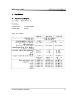
Page 19: ...over 24 hours when GPS locked 1 x 10 11 2 x 10 12 1 x 10 12 Medium stability without GPS constant temperature after 2 weeks of continuous operation 5 x 10 9 day 2 x 10 10 day 1 x 10 10 day Short term...

Page 20: ...nd 2 weeks of continuous operation 30 s 200 s 0 8 s 12 s 0 6 s 7 s If required the squelch function of the1 PPS output can be implemented on the EC1S This requires the user to download an alternative...

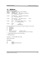
Page 21: ...ond Source e g 317 1996_18 16 20 L Format MJD Integer part Hour Minute Second Source e g _ _ _ _ _ _50399 18 20 50_U Format MJD Source e g _ _ _ _ _ _50399 762130_L The Source byte holds one ASCII cha...

Page 22: ...ive Contact Rating 30VA 250V Connector J1 Sub D HE501 9 pin female Pin settings 7 ALARM 8 ALARM 3 6 3 6 3 6 3 6 Power Supply Power Supply Power Supply Power Supply Power supply VDC 19 to 36 VDC on sta...

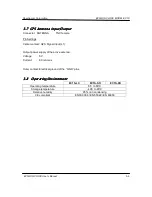
Page 23: ...ttings Center contact GPS Signal Input L1 Output power supply of the active antenna Voltage 5V Current 80 mA max Outer contact Electrical ground of the GND pins 3 8 3 8 3 8 3 8 Operating Environment O...

Page 24: ...EPSILON CLOCK MODEL EC1S Spectracom Corporation EPSILON CLOCK User s Manual 3 6...

Page 25: ...TDEV Meets the ITU G 811 recommendations when GPS locked 4 2 4 2 4 2 4 2 2 048 MHz Input 2 048 MHz Input 2 048 MHz Input 2 048 MHz Input The EPSILON CLOCK MODEL EC1S can be synchronized with an exter...

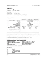
Page 26: ...User s Manual 4 2 Connector AUX1 SMA Female Pin Settings Center contact Sine wave signal Outer contact Ground Signal characteristics Signal level G 703 13 75 unbalanced Input jitter wander tolerances...

Page 27: ...by the DLE character Each message contains four distinct sections The message ID this identifies the type of message being sent The count of the number of data bytes in the message CNT The data bytes...

Page 28: ...d by the clock on the TOD output In standard mode the default message transmitted contains the current date and hour according to the codes provided herein In diagnostic mode the message transmitted c...

Page 29: ...tween the antenna and the clock generates a propagation delay of the GPS signal This delay corresponds to a time shift of the synchronizing signal This time shift can be compensated for using this com...

Page 30: ...ay Month Year Hour Minute Second Month Day Year Hour Minute Second Day of year Year Hour Minute Second MJD Modified Julian Day MJD integer part Hour Minute Second With this command the user defines wh...

Page 31: ...unction The transmission is synchronous with the 1PPS Format 1 ID 193 CNT 8 DATA day month year hour min sec source Format 2 ID 194 CNT 8 DATA day month year hour min sec source Format 3 ID 195 CNT 8...

Page 32: ...al Time 7 71 2 1 et 3 Phase Correction 8 72 4 1 et 3 Leap Second 9 73 6 1 et 4 GPS Positioning 10 74 19 1 et 3 Display 13 77 2 1 Alarm limits 14 78 10 1 Version 67 10 1 Forced holdover mode 15 79 1 1...

Page 33: ...eeded the clock is synchronized during a period of time sufficient enough to provide the frequency inside the programmed limit or the loss of synchronization is not sufficiently long to exceed the pro...

Page 34: ...tenna ms in WGS 84 Datum Ellipsoid 27 to 30 1 long 648 000 000 648 000 000 180 W 180 E Longitude of the GPS antenna ms in WGS 84 Datum Ellipsoid 31 to 34 1 long 100 000 1 800 000 1 000 m to 18 000 m A...

Page 35: ...char 23 23 hours Difference in hours and minutes between local time and the clock reference time 1 1 char 59 59 minutes Phase correction 72 8 4 0 to 3 1 long 0 1 000 ns Programmed difference between...

Page 36: ...ion 3 Command not valid 4 Remote command not authorized Forced holdover mode 79 15 1 0 1 char 1 0 Functioning mode disciplining authorized Functioning mode holdover forced Manual time setting 81 17 7...

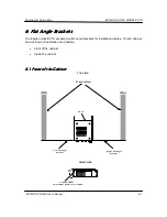
Page 37: ...EC1S accepts two flat angle brackets for installation inside a 19 inch cabinet Two methods of installation are possible Front of the cabinet Inside the cabinet 6 1 6 1 6 1 6 1 Front of the Cabinet Fro...

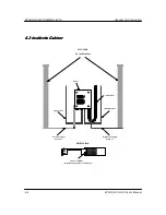
Page 38: ...s Manual 6 2 6 2 6 2 6 2 6 2 Inside the Cabinet Inside the Cabinet Inside the Cabinet Inside the Cabinet 19 inch cabinet 1pps cable 10MHz cable GPS cable EC1S Left flat angle bracket Right flat angle...

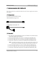
Page 39: ...cedur Procedur Procedur Procedure e e e 1 First make sure that the SAS doesn t monitor the TOD refer to the SAS instruction manual Other signals must be monitored 2 Connect the 1PPS of EC1S A on conne...

Page 40: ...EC1S Spectracom Corporation EPSILON CLOCK User s Manual 7 2 NOTE The SubD 9 pin female connector on this cable provides direct access on the RS232 remote control interface of the EC1S when this cable...

Page 41: ...Spectracom Corporation EPSILON CLOCK MODEL EC1S EPSILON CLOCK User s Manual 7 3...

Page 42: ...A 01 12 03 Creation First draft B 01 04 04 Power connection C 15 09 04 Phase noise Mechanical characteristics SDH E1 option interconnection SAS cables kit D0 09 06 08 First iteration of this Spectrac...

Page 43: ...n 95 Methodist Hill Drive Rochester NY 14623 www spectracomcorp com Phone US 1 585 321 5800 Fax US 1 585 321 5219 3 Avenue du Canada 91974 Les Ulis France www spectracom fr Phone 33 0 1 64 53 39 80 Fa...

Reviews: