


Slit Orbit Mechanism
should be selected. This enables the highest possible count rate for these parameters
and thereby a short measurement time and a good signal-to-noise ratio.
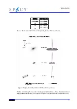
The entrance ring can be positioned directly by rotating the dial (see figure 13, “En-
trance and exit slit rings (slit combination 4-B),” page 24).The exit ring on the other
hand is positioned indirectly by the use of the entrance ring (see Figure 13: Entrance
and Exit Slit Rings (Slit Combination 4-B) page 24). Through this arrangement one can
choose the entrance and exit slits independently using the same rotary drive.
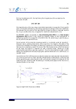
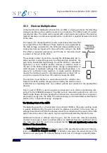
The PHOIBOS analyzers, beginning with release 5, have 8 entrance and either 2 exit slits
in the standard configuration or 3 upon request. The entrance slit positions are indic-
ated by numbers (1-8) on the external rotary dial (see Figure 12: External Rotary Dial for
Positioning page 24). The exit slit positions are indicated by letters (A-B or A, B and C).
These indicators correspond to those which appear in the region settings of the analyz-
er control software SpecsLab 2. Whenever the entrance and exit aperture is changed
the positions must be entered in the region edit dialog. The arrangement of the slits
may be other than those shown in table 4 on page 23. The actual arrangement present
in an analyzer appears in the slit selection dialog of the control software delivered with
the analyzer.
Entrance S1
Exit E2
Slit Number
Slit Size
Slit Number
Slit Size
1
0.2 x 20 mm
Free choice of
each slit
combination
except
combination
8-A
and
1-C
A
0.25 x 20 mm
2
0.5 x 20 mm
3
1 x 20 mm
4
3 x 20 mm
B
Open (for CEM each
channel is 7x21 mm )
5
7 x 20 mm
6
dia. 1 mm
C
3 x 20 mm
7
dia. 3 mm
8
dia. 7 mm
Table 4: Standard Slit Configuration
(May be different for your analyzer, please check the slit selection dialog of the Spec-
sLab2 software.)
23
Summary of Contents for PHOIBOS 100
Page 1: ...PHOIBOS Hemispherical Energy Analyzer Series PHOIBOS 100 PHOIBOS 150 3 1...
Page 6: ...Table of Contents PHOIBOS...
Page 10: ...Introduction 4 PHOIBOS...
Page 13: ...Electrical Connections Figure 2 Connection Scheme PHOIBOS 7...
Page 14: ...Components and Connections Figure 3 Analyzer Housing PHOIBOS100 8 PHOIBOS...
Page 15: ...Electrical Connections Figure 4 Analyzer Housing PHOIBOS150 PHOIBOS 9...
Page 42: ......
Page 51: ...SpecsLab Hardware and Software Installation PHOIBOS 45...
Page 52: ......
Page 62: ......
Page 78: ...Analyzer Checks Figure 33 Schematics of the 12 pin Analyzer Feedthrough 72 PHOIBOS...
Page 80: ......
Page 86: ......
Page 92: ...List of Figures Figure 39 Alignment Pin 84 II PHOIBOS...
Page 93: ...List of Figures PHOIBOS III...
Page 94: ......
Page 96: ......
Page 98: ...Index PHOIBOS...


