background image


2. OSD setup under VGA input mode (continued) 

 
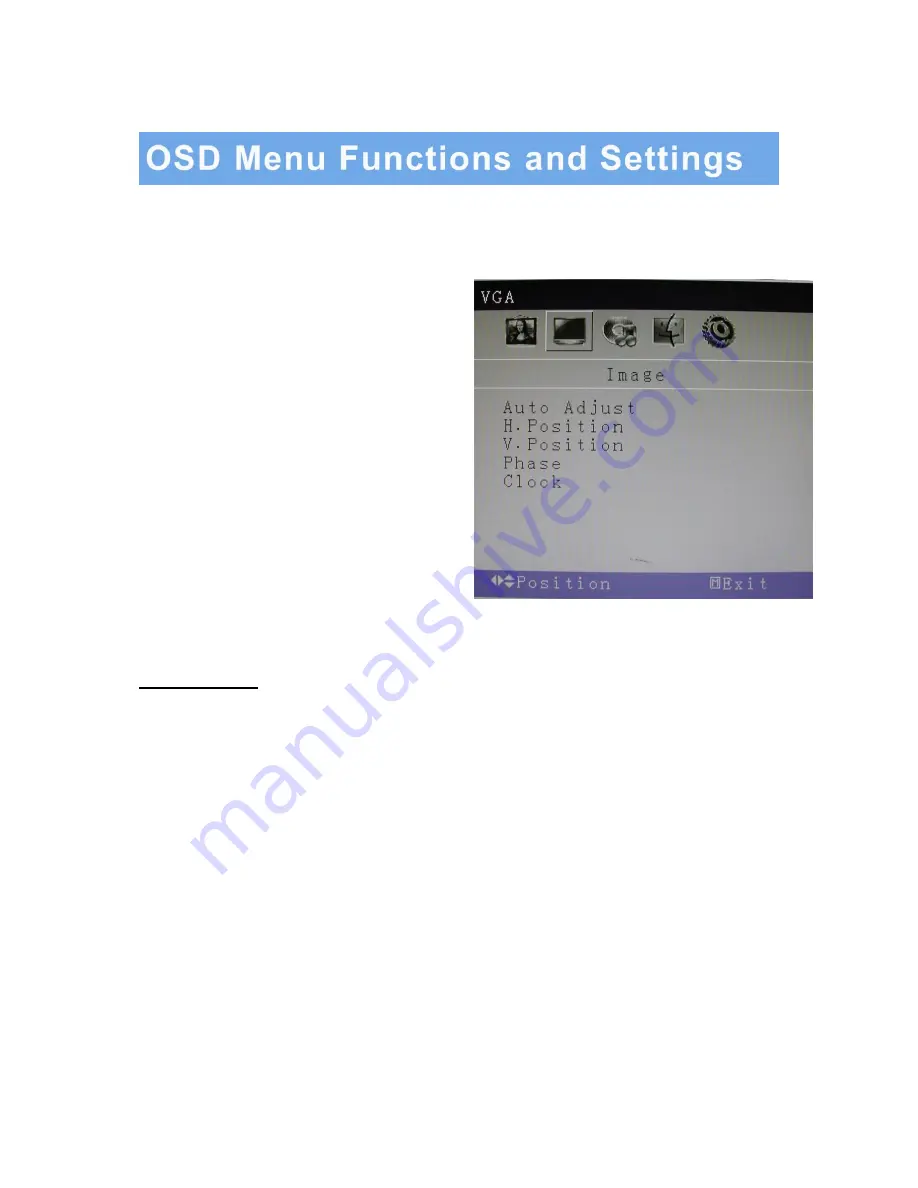
B: IMAGE MENU 


Press the MENU button to bring the menu on screen, 
and then 

Up

 / 

Down

 buttons to move left and right 

across the menu selections to highlight    the IMAGE 
menu. Press the Menu (Source) button to enter the 
(highlighted) IMAGE sub menu. 
 
 
Each additional press of the Menu/Source button 
moves the yellow highlighted sub-menu selection 
downward, moving from the bottom selection back to 
the top of the sub-menu.   
 
 
Pressing the 

Up

 / 

Down

 buttons will adjust the value 

of the highlighted item. Press the MENU button to 
save the values. Press EXIT to exit the sub-menu, 
and go back to the main menu choices. Pressing the 
EXIT button while at the top level will close the menu 
and return to normal operations. 


Adjustments 

Auto Adjust:


Automatically configures the


Phase, Clock, Vertical, and Horizontal Position   

                                                  settings 

H. Position:


Adjusts the OSD Menu’s Horizontal Position. 

V. Position:


Adjusts the OSD Menu’s Vertical Position. 

Phase:


Adjusts the signal phase to improve sharpness when the image is fuzzy. 

Clock:


If the clock setting is not exactly the same as the DVR or computer, you may observe   

                          periodic vertical bars of video noise on your image. These noise bars are usually   
                          adjusted out when an Auto Adjust is performed. If the noise bars are still present, this   
                          setting can be adjusted manually. 


13


…………………………………………………………………………… INSTRUCTION MANUAL 

Summary of Contents for M185LCBV4

Page 1: ...User Manual M185LCBV4 and M215LCBV4 LCD VIDEO MONITOR...

Page 2: ...3 CAUTION 4 FCC RF INTERFERENCE STATEMENT 5 CONNECTING WITH EXTERNAL EQUIPMENT 6 CONTROLS AND FUNCTIONS 7 16 MOUNTING GUIDE 17 D SUB CONNECTOR PIN ASSIGNMENTS 18 POWER MANAGEMENT 19 SPECIFICATIONS 20...

Page 3: ...type of power available consult your dealer or local power company 9 This product is equipped with a 3 wire grounding type plug having a third grounding pin This is a safety feature If you are unable...

Page 4: ...st only those controls that are covered by the operating instructions since improper adjustment of other controls may result in damage and will often require extensive work by a qualified technician t...

Page 5: ...TED PLACE Ventilation holes are provided on the cabinet to prevent the temperature from rising Do not cover or place anything on top of the unit AVOID HEAT Avoid placing the unit in direct sunshine or...

Page 6: ...uit different from that to which the receiver is connected Consult the dealer an experienced radio or a TV technician for help Only a shielded interface cable should be used Finally any changes or mod...

Page 7: ...Bottom and Side Panel Control Back View of Monitor A Connector Panel 1 Audio In 2 Audio Out 3 BNC Out 4 BNC In 5 VGA INSTRUCTION MANUAL 6 1 2 3 5 4...

Page 8: ...elects either the VGA or BNC input after the EXIT button is pushed and then press the MENU button to Select 2 Up Increases the volume or moves the selector indicator right in the OSD 3 Down Decreases...

Page 9: ...b menu Pressing the Up Down buttons will adjust the value of the highlighted item Press the MENU button to save the values Press EXIT to exit the sub menu and go back to the main menu choices Pressing...

Page 10: ...e Menu Source button to enter the highlighted AUDIO sub menu Pressing the Up Down buttons will adjust the value of the highlighted item Press the MENU button to save the values Press EXIT to exit the...

Page 11: ...just the value of the highlighted item Press the MENU button to save the values Press EXIT to exit the sub menu and go back to the main menu choices Pressing the EXIT button while at the top level wil...

Page 12: ...rd moving from the bottom selection back to the top of the sub menu Pressing the Up Down buttons will adjust the value of the highlighted item Press the MENU button to save the values Press EXIT to ex...

Page 13: ...top of the sub menu Pressing the Up Down buttons will adjust the value of the highlighted item Press the MENU button to save the values Press EXIT to exit the sub menu and go back to the main menu cho...

Page 14: ...ss EXIT to exit the sub menu and go back to the main menu choices Pressing the EXIT button while at the top level will close the menu and return to normal operations Adjustments Auto Adjust Automatica...

Page 15: ...e Menu Source button moves the yellow highlighted sub menu selection downward moving from the bottom selection back to the top of the sub menu Pressing the Up Down buttons will adjust the value of the...

Page 16: ...adjust the value of the highlighted item Press the MENU button to save the values Press EXIT to exit the sub menu and go back to the main menu choices Pressing the EXIT button while at the top level w...

Page 17: ...ed sub menu selection downward moving from the bottom selection back to the top of the sub menu Pressing the Up Down buttons will adjust the value of the highlighted item Press the MENU button to save...

Page 18: ...type screw that should be used do not use longer screws or the monitor may be damaged Screws 1 Before mounting the monitor remove the base riser vertical portion of the base by removing the two screws...

Page 19: ...PIN ASSIGNMENTS ACCESSORIES INSTRUCTION MANUAL 18 2 Power Cord 1 Quick Installation Guide 3 VGA Cable 4 User s Manual available through re saler...

Page 20: ...ement feature of the monitor is comprised of three stages On Green Light No Signal Flashing Green Light and Off No Light MODE COLOR MONITOR OPERATION ON Green Normal Operation NO SIGNAL Flashing Green...

Page 21: ...ndard VESA Size 100 x 100mm Stand Plastic Bezel Plastic OSD Language English French Korean and Simplified Chinese Power Consumption 20W 30W Power Supply AC110 240V 50 60 Hz Accessories Power cord Audi...

Reviews: