background image

Spearhead RC 

132/162


33


DIAGRAMS 
 

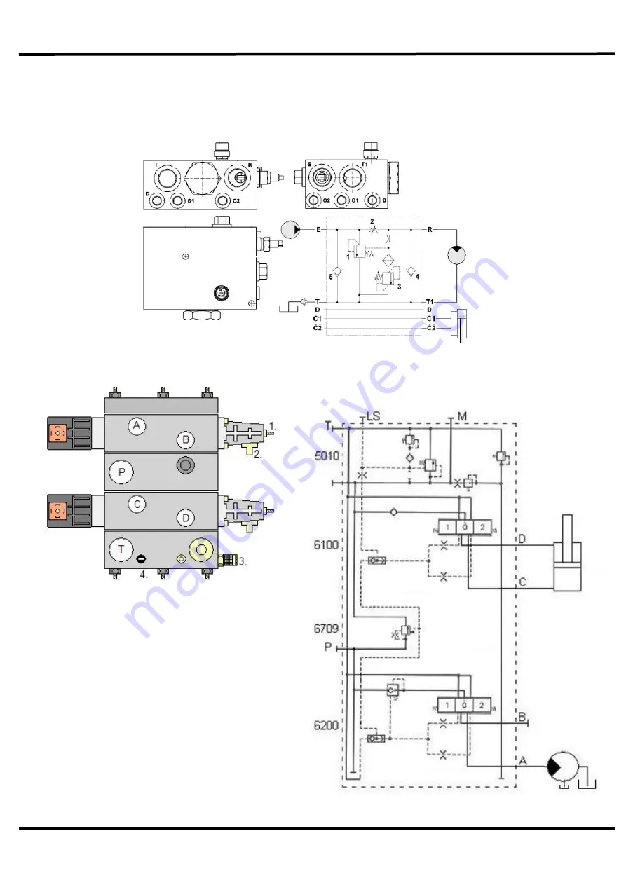
Standard Splitter Valve: 


Danfoss Splitter Valve Diagram: 


1.  Flow Adjustment 
2.  Manual Over-steering 
3.  Manometer Power Point (mini-mesh) 
4.  Safety Valve (200 bar) 


A.  Flow To Tool (regulated) 
B.  Not In Use 
C.  Cutting Angle 
D.  Cutting Angle 
P.  Pressure, Flow From Pump 
T.  Tank Connection, Depress  

T From Engine 

Summary of Contents for RC 132

Page 1: ...Spearhead RC 132 162 1 RC 132 162 ROTARY HEADS Edition 1 0 August 2017 Part No 8999108 ...

Page 2: ...by the selling dealer to verify that your machine has been registered with Spearhead Machinery Limited IMPORTANT During the initial bedding in period of a new machine it is the customer s responsibility to regularly inspect all nuts bolts and hose connections for tightness and re tighten if required New hydraulic connections occasionally weep small amounts of oil as the seals and joints settle in ...

Page 3: ... warranty does not apply to any expendable items such as blades flails bushes belts flap kits skids shields guards wear pads or pneumatic tyres 1 05 Temporary repairs and consequential loss i e oil downtime and associated parts are specifically excluded from the warranty 1 06 Warranty on hoses is limited to 12 months and does not include hoses which have suffered external damage Only complete hose...

Page 4: ...orth herein and implied warranties with respect to the goods including but not limited to merchantability and fitness for a particular purpose 3 02 The manufacturer makes no warranty as to the design capability capacity or suitability for use of the goods 3 03 Except as provided herein the manufacturer shall have no liability or responsibility to the purchaser or any other person or entity with re...

Page 5: ...d safety regulations of the respective EU Directives The Machinery Directive is supported by the following harmonized standards DS EN ISO 12100 3rd edition 2011 Safety of Machinery General principles for design Risk assessment and risk reduction DS EN 953 A1 4th edition 2010 Safety of Machinery Guards General requirements for the design and construction of fixed of moveable guards DS EN ISO 4413 1...

Page 6: ...The RC Rotary Heads 25 Work Position With RC Rotary Heads 26 Field Of Application 28 Driving Directions For Hedge Cutting 30 Safety Distances 31 Diagrams 33 Maintenance 37 Routine Maintenance Schedule 38 Belt Tension Control 39 Belt Diagrams 41 Lubrication 42 Pump And Motor Failure 45 Blades 46 Bushings And Bearings 47 Storage 48 Correct Lifting Of The RC Rotary Head 49 Noise Measuring 50 Supplier...

Page 7: ...Spearhead RC 132 162 7 Rotor Centre RC 162 66 Tensioning System RC 132 68 Tensioning System RC 162 69 Motor Transmission RC 132 70 Motor Transmission RC 162 72 S180020 201 Marketing Safety Decals 74 ...

Page 8: ...er is situated beneath the lower rotor The hedge cutter is supplied with an adaptor for mounting on various vehicles The belt drive is fully covered by a safety steel cover Gaining access to the belt drive for maintenance purposes requires loosening 2 bolts Important Note The information contained in this manual is correct at the time of publication However in the course of constant development ch...

Page 9: ...azardous situation which could result in damage to the machine and equipment if not observed correctly NOTICE Specific or general information considered important or useful to emphasise LEFT HAND LH RIGHT HAND RH These terms are applicable to the machine when fitted to the tractor and viewed from the rear these terms also apply to the tractor references SERIAL PLATE All machines are equipped with ...

Page 10: ...s have been tested on the following reach arm systems Spearhead Twiga MID PRO FLEX with tractors from 4400kg wheelbase of 250 cm and a track width of 200 cm measured from to the outer edge of the tyre till tractors of 5500kg wheelbase of 280cm and a track width of 250cm measured from to the outer edge of the tyre Because there are different types of tractor structures and differences in weight dis...

Page 11: ...rable to use external weights but liquid can be added to around 75 of the tyre volume water with anti freeze or the heavier Calcium Chloride alternative can be used Addition of weights care should be taken in selecting the location of the weights to ensure they are added to a position that offers the greatest advantage Front axle locking check with tractor manufacturer NOTE The advice above is off...

Page 12: ... safety shoes and goggles Dispose of oil and grease according to regulation Immediately after finishing work all safety and protection units must be installed and activated again Before any use the sections Putting Into Operation by the manufacturer of the tractor vehicle must be carefully followed Safety Advice For The Head Of Operation User It is of the most utmost importance to be familiar with...

Page 13: ...s running Warning Stay clear of rotating saw blades Warning Do not remove open guard when parts are rotating Warning Stop engine and remove key before performing maintenance or repair work Warning Check all nuts and bolts are tight every 8 hours retighten if required Warning Carefully read operators manual before handling this machine Observe instructions and safety rules when operating Warning Do...

Page 14: ...ublic highway advising them of the time and location of the intended work asking what is required by the way of signs and procedure Non authorised placement of road signs may create offences under the Highways Act Suggested Warning Signs Required The reach arm machine must be fitted with a white on blue 600mm diameter Keep Left direction arrow A white with red border Hedge Cutting warning triangle...

Page 15: ...that the following personal protective equipment is worn when the operating and or maintaining this machine coveralls safety boots safety glasses hearing protection safety helmet protective gloves Although the information stated here covers a wide range of safety subjects it is impossible to predict every eventuality that can occur under different circumstances whilst operating this machine No adv...

Page 16: ... 132 162 16 COMPONENTS IDENTIFICATION a Main Body b Motor c Support Wheel d Guard For Belt Drive e Branch Guide f Front Flap Blade Unit Components a Blade b Upper Lower Blade Carriers c Blade Bolt A B C D E A B C F ...

Page 17: ...stable Power Requirement 13 3 kW 18 3 Hp Operation Speed 2500 rpm 2500 2600 rpm Max Oil Pressure 200 bar 20 MPa 280 bar 28 MPa Max Leak Pressure 0 1 5 bar 0 0 15 MPa Max Return Pressure 15 bar 1 5 MPa Oil Filtering Standard 10 micron Recommended Hydraulic Oil Cold Climate HLP 46 Warm Climate HLP 68 Designed For Hedges Branches Sizes 0 30 mm 0 40 mm Allowed Angles From 15 to 90 Field Of Application...

Page 18: ...or missing Inspect work area for wire steel posts large stones and other dangerous materials and remove before starting work Beware of the danger of overhead power cables The operator must be aware of the maximum height and reach of the machine when working under power cables The minimum height for 11 000 and 22 000 volt cables is 5 2 metres from the ground When fully extended the machine may well...

Page 19: ...se a machine that is poorly maintained or has guards that are damaged or missing Never allow an inexperienced person to operate the machine without supervision Never use fit a machine onto a tractor if it doesn t meet the manufacturer s specification Never use a machine if the hydraulic system shows signs of damage Never allow children to play on or around the machine at any time Never attempt any...

Page 20: ...ommended speed and drive with a safe speed that is adjusted to the terrain and other possible obstacles Tool Start Choose low engine RPM Make sure that the surrounding area is secured Warm start start the tool Cold start never start the tool at maximum speed Let the tool run without much strain for approximately 15 minutes to heat up the oil Slowly increase rpm until the correct oil amount is reac...

Page 21: ...ch or with bolts Spearhead RC Rotary Heads are designed specifically for Spearhead s various reach arm machines RC Rotary Heads are designed to be mounted on tractors via a suitable armsystem The RC132 has a work width of approximately 130cm with a weight of 110kg The RC162 has a work width of approximately 160cm with a weight of 150kg If necessary ballast can be mounted on the vehicle or the reac...

Page 22: ...d the head Photo 2 After connecting the RC rotary head to the reach arm the hydraulic hoses can then be attached Pay close attention to the correct attachment Slowly raise the machine Let it run for 5 minutes stop the machine and inspect all connections for leakage Dismounting the RC rotary head is done in reverse order ...

Page 23: ...essurized 0 bar tank connection THIS MUST NEVER BE CONNECTED TO RETURN PRESSURE Medium Sized Hose Marked Red Connected to Pressure P with a maximum of 200 bar RETURN Largest Sized Hose Marked Green Connected to Tank T with a maximum back pressure of 15 bar All machines supplied by Spearhead have hose connections with the following stickers ...

Page 24: ...ending on whether your reach arm machine is Left hand LH or Right hand RH build influences a The rotational direction of the blades b The location of the guide wheel LH Mounted Machines RH Mounted Machines Direction of travel Direction of travel A A B B ...

Page 25: ... is mounted if supplied For Spearhead machines with slewing ability the reach arm should be slewed behind the tractor Be mindful if the reach arm is lifted to the transportation stop that it doesn t hit the cab of the vehicle or will hit the cab during transportation The RC rotary head and reach arm are now ready for transportation Transport position shown on a Spearhead Twiga 320 Right hand build...

Page 26: ... Adjust the cutting angle for the first cut Always start from the bottom vertically or in a suitable angle Choose the most suitable forward drive depending on the condition of the hedge surface traffic and visibility 3 Adjust the angle for the second cut Keep the same angle as for the first cut ...

Page 27: ...h a horizontal cut If the hedge is wider than the rotary head you get the best result by starting the cut close to the vehicle 5 RC Rotary Heads are NOT constructed for lawn mowing 6 NEVER turn the rotary head towards the tractor This is very dangerous ...

Page 28: ...e the blades cut directly at the branches Where possible the blades have to cut vertical in the direction of travel This prevents the blades from bending during work If smaller branches and other unwanted material get stuck the machine and vehicle must be stopped and the ignition key removed before attempting to clean the blades Under no circumstances is the machine to be used to cut down trees Th...

Page 29: ...facing the user When responsible for the machine always follow the rules below Always inspect the work area before starting work and remove potentially dangerous material Never use the machine close to persons or animals Read the section Safety Distances Make sure that all cab covers are secured and that the windows remain closed during work If the vehicle has no cab always wear safety glasses and...

Page 30: ...ts the blades from bending during work It can be an advantage to use the Branch Guide optional equipment at the bottom of the rotary head to lift smaller twigs closer to the blades Caution must be taken when working close to the ground Smaller adjustments of the cutting angle can be done when driving but it is recommended to stop working when making larger adjustments To prevent the blades from bl...

Page 31: ...TALLY Illustration 1 Safety zone at 1 metre cutting height horizontally Cutting Height Horizontally Safety Radius Safety Distance From The Front 0 1m 5 m 10 m 1 1 1 2 m 6 m 11 m 1 2 1 3 m 7 m 12 m 1 3 1 4 m 8 m 13 m 1 4 1 5 m 9 m 14 m 1 5 m 10 m 15 m ...

Page 32: ...ICALLY Illustration 2 Safety zone at 1 metre cutting height vertically Cutting Height Vertically Safety Radius Safety Distance From The Front 0 1m 5 m 10 m 1 1 1 2 m 6 m 11 m 1 2 1 3 m 7 m 12 m 1 3 1 4 m 8 m 13 m 1 4 1 5 m 9 m 14 m 1 5 m 10 m 15 m ...

Page 33: ...s Splitter Valve Diagram 1 Flow Adjustment 2 Manual Over steering 3 Manometer Power Point mini mesh 4 Safety Valve 200 bar A Flow To Tool regulated B Not In Use C Cutting Angle D Cutting Angle P Pressure Flow From Pump T Tank Connection Depressurized T From Engine ...

Page 34: ...Spearhead RC 132 162 34 Hydraulics Diagram RC 132 Hydraulic Diagram For Correct Fitting ...

Page 35: ...32 162 35 Belt Diagrams RC132 RC162 1100 900 Nm 950 720 Nm 1100 900 Nm 950 720 Nm Nm New Existing RC132 Left Model Nm New Existing RC132 Right Model Nm New Existing RC162 Left Model Nm New Existing RC162 Right Model ...

Page 36: ...essurized 0 bar tank connection THIS MUST NEVER BE CONNECTED TO RETURN PRESSURE Medium Sized Hose Marked Red Connected to Pressure P with a maximum of 200 bar RETURN Largest Sized Hose Marked Green Connected to Tank T with a maximum back pressure of 15 bar All machines supplied by Spearhead have hose connections with the following stickers ...

Page 37: ...repealed To be exact bypassing the safety advice may result in Endangering persons at non secured work areas Malfunction of important machine functions Malfunction of prescribed methods for maintenance and service Endangering persons following mechanical or chemical impact Endangering the environment following a hydraulic oil leak Only carry out service with machine shut off The procedure for stop...

Page 38: ...de carrier s tighten if required Check headstock mounting bolts for tightness tighten if required After 10 hours of Use New Machine Check gearbox oil level s top up if required Check blades for damage Check blade bushes for wear Check headstock mounting bolts for tightness tighten if required MACHINE COMPONENT MAINTENANCE INTERVAL Weekly Fortnightly Monthly Annually Motor Check mounting bolts tigh...

Page 39: ...62 After 3 5 hours of operation the belt has given in and must be checked again The tension may now have changed now they ve been used They must be tensioned now to RC132 720 Nm RC162 900 Nm Recommended Tools Belt Measurer Optikrik II 1 pc 13mm Ring Fork Spanner 2 pc 19mm Ring Fork Spanner Work Gloves Safety Shoes Procedure Loosen the two caps bolts and raise the cap Check the Nm belt setting with...

Page 40: ...ions please contact the Spearhead Service Department and we will help out with advice and supply the correct measuring tool Loosen the two bolts Raise the cap Loosen counter nut and adjust belts Check belt tension at the middle of the belt with belt measurer 200155 0 ...

Page 41: ...RC162 Tool For Checking Belt Tension OPTIKRIK II Part No 200155 0 1100 900 Nm 950 720 Nm 1100 900 Nm 950 720 Nm Nm New Existing RC132 Left Model Nm New Existing RC132 Right Model Nm New Existing RC162 Left Model Nm New Existing RC162 Right Model ...

Page 42: ...tings to be in good order Any damages or leaks must be rectified immediately this is part of the daily maintenance and is your responsibility to ensure a long reliable working life Spearhead s hydraulic system works at very high pressure When replacing hoses use only genuine hoses A burst hose could be very dangerous When replacing hoses avoid twisting fitting use two spanners to slacken and tight...

Page 43: ...to overtightening Oil Supply Daily check the oil level in tank reservoir before starting up It is good practice to constantly keep an eye on the tank level gauge this can be seen from the tractor seat as a pipe burst could empty the tank within minutes A pump or motor starved of oil will be damaged beyond repair Replace oil if signs of contamination occur discolouration Use the correct and suitabl...

Page 44: ...utions Avoid prolonged and repeated contact with oils particularly used engine oils Wear protective clothing including impervious gloves where practicable Avoid contaminating clothes with oil particularly those next to the skin Overalls must be cleaned regularly Discard heavily soiled clothing or oil impregnated footwear First aid treatment should be obtained immediately for open cuts and wound Ap...

Page 45: ... on the ground as changes in pressure are directed back to the pump and may result in malfunction Avoid letting the rotor hit an object such as a rock as this will cause pressure changes Never transport the machine with the engine running Never choose a higher PTO RPM oil flow than recommended Never work with more than the recommended PTO speed oil flow this will result in overheating NOTE The eng...

Page 46: ...the blades show signs of severe wear damage or cracks then they must be replaced immediately Never attempt to weld the blades as this will leave them brittle and extremely dangerous Never take a risk with the blades if in doubt replace them When the sap disappears from the branches the end result will become more frayed When operating off growth season the blades will wear out faster The best resu...

Page 47: ... signs of wear and tear then they must be replaced All bushes bolts and bearings can be supplied from Spearhead s Spare Parts Department WARNING Bushes MUST be replaced if they have cracks or show signs of wear and tear NEVER compromise when it comes to safety When replacing blades also change the bushes blade bolts and nuts ...

Page 48: ...important to store the machine covered from rain or sunlight The machine must be placed horizontally on a level surface or pallet Make sure that the machine is unable to tip or fall down when stored Find a suitable storage place and support the machine Never leave hydraulic hoses on the floor They pose a risk of stumbling Place all hoses on the machine or rotary head Always store the machine in cl...

Page 49: ...e blades and belts Remember that the RC Rotary Head all models is constructed to resist even the toughest conditions and that with some care and attention it will supply you with many years of problem free service To avoid problems and ensure that it is covered by the guarantee always use original spare parts and make sure that the machine is not used for anything else than described in this manua...

Page 50: ...he machine during normal working conditions with a Delta OHM noise measurer type HD 8701 The energy A weighted sound pressure is lower than 83 dB A The test has been done at a distance of 1 metre from the machines critical noise maker and at a height of 1 5m above the ground ...

Page 51: ...lford Priors Evesham Worcestershire Postcode WR11 8SW Telephone 44 0 1789 491860 Email enquiries spearheadmachinery com CE Declaration Contact Spearhead Machinery Limited Telephone 44 0 1789 491860 Email enquiries spearheadmachinery com Machine No Spearhead RC132 Spearhead RC162 Machine Type Rotary Hedge Cutter Delivery Date Delivery Year 2017 ...

Page 52: ... BANS DIRECTIONS Never attempt any maintenance or adjustment without first disengaging the PTO hydraulic pump Only authorised personnel are allowed to do maintenance on the equipment Read this manual carefully before using the machine ...

Page 53: ...chine must be disassembled and the parts separated as following Category Example of Parts Rubber Plastic Hoses Rubber Guards Stabilisers Plastic Strips etc Technical Components Pumps Motors Hydraulic Hoses etc Pure Metal Plates Pipe Guards Blades Pulleys etc Disposal must be carried out according to present national and EC legislations ...

Page 54: ...h oil to the correct level Oil leak in pressure hose Check machine for leaks Oil pump filter is blocked Replace the filter element Branches get frayed Larger branches than recommended Never exceed the recommended maximum branch sizes of the hedge cutter Working during winter time Work during growth season Cutting result skewed hacked Defective rotor bearings Change bearings Rotor damaged bent Chan...

Page 55: ...ilability and arrangement of dispatch Ensure you or your dealer has sufficient cover for parts requirement outside factory hours Important Note The information contained in this manual is correct at the time of publication However in the course of constant development changes in specification are inevitable Should you find the information given in this book different to the machine it relates to p...

Page 56: ...Spearhead RC 132 162 56 MAIN FRAME OVERVIEW RC 132 ...

Page 57: ...ING RAIL 1 11 8481501 BLADE CHANGE TOOL 1 12 8486002 LYNCH PIN 1 13 8481505 BELT DRIVE GUARD 1 14 8481002 WHEEL SHAFT 1 15 8486001 SUPPORT WHEEL 1 16 8482003 BOLT 2 17 8481506 BRANCH GUIDE 1 18 8482002 CARRIAGE BOLT 14 19 8481004 THREADED HINGE BAR 1 20 8488001 FRONT FLAP 2 21 8362006 BOLT 4 22 2770434 FLAT WASHER 8 23 8362005 NUT 4 24 8222011 WASHER HD 1 25 8222006 BOLT 4 26 8222005 SPRING WASHER...

Page 58: ...Spearhead RC 132 162 58 MAIN FRAME OVERVIEW RC 162 ...

Page 59: ...FOR FLOWDIVIDER OPTION 1 12 Rexroth mængdedeler FLOWDIVIDER OPTION 1 13 RC 162 Twiga adapter TWIGA MOUNT BRACKET 1 14 Hjul SUPPORT WHEEL 1 15 RC162 01 018 WHEEL SHAFT 1 16 RC162 modholds vkt BLADE CHANGE TOOL 1 17 RC162 01 014 FLAP GUARD MOUNTING RAIL 1 18 RC162 01 016 SUPPORT RAIL 1 19 M6x16 BOLT 5 20 Brædebolt M6x20 CARRIAGE BOLT 16 21 M6 Låsemøtrik LOCK NUT HIGH 16 22 M12x16 CH BOLT 2 23 M16x50...

Page 60: ...Spearhead RC 132 162 60 ROTOR OUTER 2 pcs ON MACHINE RC 132 ...

Page 61: ...0162001 0 CIRCLIP 1 6 8482007 BOLT SPECIAL 10 9 6 7 8484004 PULLEY 1 8 8481007 MOUNT DISK 1 9 8487001 BLADE 6 10 8481008 7770812 BLADE BUSH 6 11 8481009 7770810 BLADE BOLT 6 12 8481011 LOWER BLADE CARRIER 1 13 8482008 LOCK NUT 6 14 8481010 SPACER 2 15 8484005 KEY 1 16 8482009 LOCK NUT 10 9 6 17 8482010 BOLT 1 18 8481507 ROTOR SHAFT WITH BLADE CARRIER OUTER 1 19 8481508 UPPER BLADE CARRIER 1 ...

Page 62: ...Spearhead RC 132 162 62 ROTOR OUTER 2 pcs ON MACHINE RC 162 ...

Page 63: ... Lameltætning METAL SEAL 1 6 Ø68 låsering CIRCLIP 2 7 RC162 02 005 BLADE BUSH 6 8 RC1621 kniv 8777809 BLADE 6 9 RC162 06 003 LOWER BLADE CARRIER 1 10 RC162 06 UPPER BLADE CARRIER 1 11 RC162 02 001 PULLEY 1 12 RC162 02 004 SPACER 2 13 RC bolt BLADE BOLT 6 14 Møtrik M12 DIN 980 7770811 LOCK NUT 6 15 M10x55 DIN931 BOLT SPECIAL 10 9 6 16 Møtrik M10 DIN 980 LOCK NUT 10 9 6 17 RC162 02 002 MOUNT DISK 1 ...

Page 64: ...Spearhead RC 132 162 64 ROTOR CENTRE 1 pcs ON MACHINE RC 132 ...

Page 65: ... CIRCLIP 1 6 8482007 BOLT SPECIAL 10 9 6 7 8484004 PULLEY WITH CLAW 1 8 8481007 MOUNT DISK 1 9 8487001 BLADE 6 10 8481008 7770812 BLADE BUSH 6 11 8481009 7770810 BLADE BOLT 6 12 8481011 LOWER BLADE CARRIER 1 13 8482008 LOCK NUT 6 14 8481010 COVER FOR BEARING HOUSING 2 15 8484005 KEY 1 16 8482009 LOCK NUT 10 9 6 17 8482010 BOLT 1 18 8481509 ROTOR SHAFT WITH BLADE CARRIER CENTRE 1 19 8481508 UPPER B...

Page 66: ...Spearhead RC 132 162 66 ROTOR CENTRE 1 pcs ON MACHINE RC 162 ...

Page 67: ... Lameltætning METAL SEAL 1 6 Ø68 låsering CIRCLIP 2 7 RC162 02 005 BLADE BUSH 6 8 RC162 kniv BLADE 6 9 RC162 06 003 LOWER BLADE CARRIER 1 10 RC162 06 UPPER BLADE CARRIER 1 11 RC162 03 002 PULLEY WITH CLAW 1 12 RC162 02 004 COVER FOR BEARING HOUSING 2 13 RC bolt BLADE BOLT 6 14 Møtrik M12 DIN 980 LOCK NUT 6 15 M10x55 DIN931 BOLT SPECIAL 10 9 6 16 Møtrik M10 DIN 980 LOCK NUT 10 9 6 17 RC162 02 002 M...

Page 68: ... NO DESCRIPTION QTY 1 8481510 TENSION PLATE RH LH 1 2 8481013 SHAFT FOR BELT TENSION 1 3 8481014 PULLEY FOR BELT TENSION 1 4 200120 0 BEARING 2 5 200121 0 CIRCLIP 1 6 8482011 BOLT 1 7 8362007 BOLT 1 8 2770536 NUT 1 9 200119 0 CIRCLIP 1 10 8222003 SPRING WASHER 1 ...

Page 69: ...1 RC162 08 TENSION PLATE RH LH 1 2 RC162 07 001 SHAFT FOR BELT TENSION 1 3 RC162 07 002 SHAFT FOR BELT TENSION 1 4 6206 leje BEARING 2 5 62mm låsering CIRCLIP 1 6 Ø30 låsering CIRCLIP 1 7 M12x40 CH BOLT 1 8 M12x120 sætbolt BOLT 1 9 M12 møtrik NUT 1 10 Ø12 Fjederskive SPRING WASHER 1 ...

Page 70: ...Spearhead RC 132 162 70 MOTOR TRANSMISSION RC 132 ...

Page 71: ... 8483001 MOTOR 1 5 8486003 CLAW 1 6 8481015 SPACER 1 7 8482012 BOLT 4 8 8486003 ELASTIC ELEMENT 1 9 8484007 KEY 1 10 8143002 PORT ELBOW 2 11 8143004 BANJO CONNECTOR 1 12 8143003 BANJOBOLT 1 4 1 13 8143005 SEAL 3 14 NOT AVAILABLE USE NO 10 3 15 8222003 SPRING WASHER 3 16 8142003 WASHER HD 3 17 200109 0 BOLT 3 ...

Page 72: ...Spearhead RC 132 162 72 MOTOR TRANSMISSION RC 162 ...

Page 73: ... 1 CLAW HOUSING 1 2 RC162 10 SPACER 1 CLAW 4 RC162 10 003 MOTOR 1 5 Klokobling KEY 1 6 Bondioli motor ELASTIC ELEMENT 1 7 Pasfeder 8mm SPRING WASHER 1 8 Gummi element BOLT 1 9 Ø12 Låseskive FLAT WASHER 2 10 M12x30 bolt BOLT 2 11 Ø13 Facetskive FLAT WASHER 2 12 M10x30 SPRING WASHER 3 ...

Page 74: ...RIPTION QTY 1 8770373 SPEARHEAD DECAL 1 2 8770361 ROTARY DANGER DECAL 1 3 8770359 PYLONS DECAL 1 4 8770357 FLYING DEBRIS DECAL 1 5 8770306 BOLTS TIGHT DECAL 1 6 8770358 REMOVE KEY READ BOOK DECAL 1 7 8770363 READ MANUAL DECAL 1 8 8770356 BELTS DECAL 1 9 8770451 DON T STAND ON MACHINE DECAL 1 ...

Page 75: ...Spearhead RC 132 162 75 ...

Page 76: ...Spearhead RC 132 162 76 ...

Reviews: