


Spearhead Outfront Flail
13
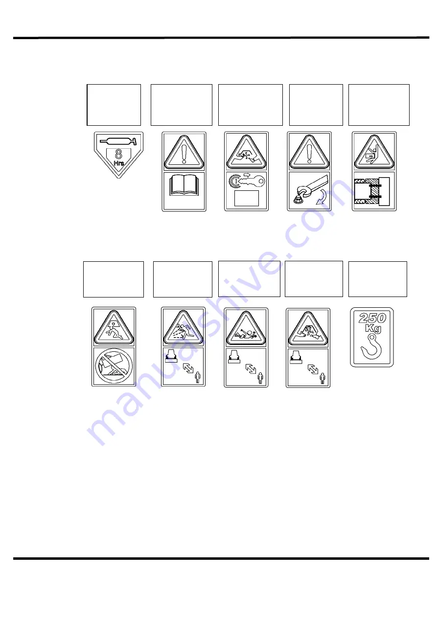
Figure 2.4.2
Any safety decals which are found to be missing should be replaced.
Grease point:
Grease every 8
hours
Warning :
Read instructions
before use
Safe Working :
Remove ignition
key before
working on
machine
Warning :
Keep nuts
tight
Crushing hazard:
Stay clear of
immediate area
around machine
Falling hazard :
Do not go under
machine when
raised
Thrown debris
hazard : Keep
your distance
Shaft
entanglement
danger : Keep
your distance
Safe Working :
Keep your
distance
Lift point :
250Kg
Summary of Contents for Outfront Flail 130
Page 1: ...Spearhead Outfront Flail 1 OUTFRONT 130 160 FLAIL Edition 2 0 April 2016 Part No 8999090 ...
Page 16: ...Spearhead Outfront Flail 16 Figure 3 2 2 ...
Page 30: ...Spearhead Outfront Flail 30 Figure 8 1 2 Spearhead Scoop flail ...
Page 33: ...Spearhead Outfront Flail 33 77 021 02 130 COWL ASSY ...
Page 34: ...Spearhead Outfront Flail 34 77 021 02 130 COWL ASSY ...
Page 35: ...Spearhead Outfront Flail 35 77 022 02 130 ROLLER ASSY ...
Page 37: ...Spearhead Outfront Flail 37 77 563 09 130 DRIVE ASSY ...
Page 38: ...Spearhead Outfront Flail 38 77 563 09 130 DRIVE ASSY ...
Page 39: ...Spearhead Outfront Flail 39 77 563 08 160 COWL ASSY ...
Page 40: ...Spearhead Outfront Flail 40 77 563 08 160 COWL ASSY ...
Page 41: ...Spearhead Outfront Flail 41 72 121 22 160 ROLLER ASSY ...
Page 43: ...Spearhead Outfront Flail 43 77 563 07 160 DRIVE ASSY ...
Page 44: ...Spearhead Outfront Flail 44 77 563 07 160 DRIVE ASSY ...
Page 45: ...Spearhead Outfront Flail 45 77 560 01 CASTOR WHEELS ASSY ...
Page 46: ...Spearhead Outfront Flail 46 77 567 01 DECALS ENGINEERING ...
Page 47: ...Spearhead Outfront Flail 47 S181013 01 DECALS SPEARHEAD ...
Page 48: ...Spearhead Outfront Flail 48 ...


