background image

I.


Introduction 

1.


Intended Application. To Be Installed Only in Restricted Access Areas 

(Dedicated Equipment Rooms, Equipment Closets, or the like) in Accordance 
with Articles 110-18, 110-26, and110-27 of the National Electrical Code, 
ANSI/NFPA 70. The equipment must be operated and maintained only by trained 
personnel. 

2.


Installation in any other enclosure, like a rack, requires the speaker to connect 

via Class 1 wiring to the Speakon connector on the faceplate. 

3.


Enclosure construction.  

a.


This amplifier should only be installed in a wood (solid, plywood, 

particle board, etc) or metal enclosure.  It should not be installed in a 
plastic enclosure.  

b.


The speaker cabinet must be 2 cu ft or larger to allow sufficient air for 

cooling. Allow at least 6 inches of space around the vents in the back of 
the amplifier. Do not block the circulation of air around the amplifier. Do 
not place flammable materials over or near the amplifier.  

c.


Sound deadening material should not be installed in contact with any 

electrical connections on the amplifier or speaker. 

d.


Sound deadening material should be flame rated HB or better by UL 

LLC. 

e.


Suitability of handles or mounting points should be determined by an 

appropriate testing facility. 

f.


 All exposed edges and surfaces should be smooth and rounded to 

prevent injury during handling. 

4.


Installation in the cabinet. It is recommended that the amplifier be recessed 

into the speaker cabinet 3/8” to prevent abrasion and possible damage to the 
heatsink and connectors. It is not necessary or recommended to create a separate 
subenclosure for the amplifier in the speaker cabinet. If a ported cabinet, 
installation close to the port is recommended for best thermal capacity. 

5.


A copy of these safety instruction should be provided with each loudspeaker 

system. 

Summary of Contents for SP Series

Page 1: ...Installation and Operation Instructions for SP Series Plate Amplifiers SpeakerPower Inc 3001 S Harbor Blvd Santa Ana CA 92704 ...

Page 2: ...into the apparatus the apparatus has been exposed to rain or moisture does not operate normally or has been dropped 15 WARNING To reduce the risk of fire or electric shock do not expose this apparatus to rain or moisture 16 The lightning flash with arrowhead symbol within an equilateral triangle is intended to alert the user to the presence of uninsulated dangerous voltage within the product s enc...

Page 3: ...he amplifier Do not block the circulation of air around the amplifier Do not place flammable materials over or near the amplifier c Sound deadening material should not be installed in contact with any electrical connections on the amplifier or speaker d Sound deadening material should be flame rated HB or better by UL LLC e Suitability of handles or mounting points should be determined by an appro...

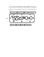
Page 4: ...ECT SIGNAL 6 Parts Check List The amplifier comes with an appropriate AC power cord The user must provide input and speaker cabling appropriate for the application 7 Panel Layout The arrangement of the connectors may differ from model to model II DSP Connector Mute switches XLR input Volume Power Fuse Voltage Select Power In out ...

Page 5: ...r tool is the AMP 318851 1 a Rack mounting or any enclosure other than a speaker cabinet Speaker connections must be made with Class 1 wiring to the Speakon connector on the faceplate 2 We recommend using twisted pair wiring to the speakers of at least 16 gauge Both and wires are hot so they should not be allowed to touch any other wire the amplifier cabinet or ground The channels are brought out ...

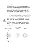
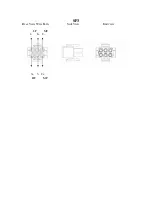
Page 6: ...SP3 Rear View Wire Exits Side View End view LF MF 1 1 2 3 3 2 HF MF ...

Page 7: ...Some models do not have a voltage selector switch They must be connected to the supply indicated on the amplifier markings 2 Powering up the amplifier Before turning on the amplifier check to make sure the voltage selector switch is set to the proper range for your service Connect the input lower the volume control and turn on all preceding equipment in the signal chain To turn on power press the ...

Page 8: ...s to enter Setup mode 9 Set the parallel port to EPP mode in CMOS Setup 10 Save setup and boot to Windows 11 Unzip the files in ALE5 2 zip Run Setup exe to install 12 Unzip the files in DASDCT3 1 zip Run Setup exe to install 13 Unzip the files in softwareupdate zip into the DCT3 1 folder Overwrite any existing files of the same name 14 To Load an Existing Configuration 15 Plug interface cable from...

Page 9: ...ss OK 29 If you created filters before and saved them as a filter parameter par file you may reload them from the FILE menu and proceed to modify them as shown in the next steps 30 EDIT menu select Edit Filter Parameters 31 Add filters to table 32 EQ filters Remember when adding eq filters that bandwidth in the ALE program is expressed in Hz not octaves If translating from a processor that express...

Page 10: ...e file to the existing folder DAP Config Tool 2 0 38 Repeat steps 2 8 for each channel of the amplifier 39 Generate limits 40 Set Threshold 1 to 155dB 90 ref full output_ to gate out the noise floor Expansion slope 10 41 Set threshold 2 based on 1W output limit 95 5 Compression slope 30 42 Region 2 1 1 43 Don t forget to set Integration Attack and Release times in DCT 44 Operate DSP 45 Plug interf...

Page 11: ...beling 1 is 3 and 3 is 1 Or to put it another way To the outside world ch1 is LF and Ch3 is HF 55 Select PAGE 2 56 Select Vol Set the volume offset between channels using the sliders Close the dialog box 57 Select Delay3 button Add desired delay to channels Each increment is 10 4uS Close dialog box 58 Select SAVE Enter a new unique file name for this configuration 59 You may now unmute the amplifi...

Reviews: