background image


Contents 


1.


Introduction  ………………….…………………………….……..………….

p3


2.


Caution …………………………………………………….………………….…..

p3


3.


Delivery control  …………………………………………........................

p4


4.


Technical description  …………………………….……………………..

p4


Technical characteristics   
Outside 
Inside 
explored view 
Wire control operation 

General diagram of the refrigerating circuit 
Safety and control systems 
 

5.


Installation  ……………………….………………………………….......

p14


Rules of installation 
Hydraulic connections 
Electric connections 
 

6.


Water flow and refrigerating circuit pressure........................

p17


7.


Environment problem  ………………………………………............

p18


8.


Maintenance and inspection  ……………….…………………..…

p19


9.


Electric diagram  ……………………………………………….……..…

p21


Summary of Contents for SHP-100P

Page 1: ...Directions for installation and maintenance SHP 60P SHP 80P SHP 100P SHP 120P SHP 140P SHP 170P SHP 190P ...

Page 2: ...ide explored view Wire control operation General diagram of the refrigerating circuit Safety and control systems 5 Installation p14 Rules of installation Hydraulic connections Electric connections 6 Water flow and refrigerating circuit pressure p17 7 Environment problem p18 8 Maintenance and inspection p19 9 Electric diagram p21 ...

Page 3: ...th the appliance Cleaning and user maintenanceshall not be made by children without supervision If the appliance is fixed wiring the appliance must be fitted with means for disconnection from the supply mains having a contact separation in all poles that provide full disconnection under over voltage category III conditions and these means must be incorporated in the fixed wiring in accordance with...

Page 4: ...W 6 8 3 10 12 14 17 19 5 Heating nominal intensity A 5 3 7 2 9 0 10 8 12 8 15 19 Cooling absorptive power kW 1 2 1 6 2 0 2 3 2 7 3 2 3 5 Cooling restored power kW 4 3 5 8 7 2 8 1 9 7 11 5 14 5 Cooling nominal intensity A 5 8 7 8 9 8 11 5 13 6 16 20 3 Air flow m3 H 1700 1700 2000 2000 3200 4000 4000 Noise level d B A 48 49 50 51 52 53 54 Refrigerant gas R410a R410a R410a R410a R410a R410a R410a Rat...

Page 5: ...r 5 Connection for water outlet 6 Wire connection for power supply 7 Connection for water intlet 8 Rear net 9 Evaporator 10 Fan 11 Compressor 12 High and low pressure interruptor 13 Titanium heat exchanger 14 Temperature sensor of swimming pool water 15 Four way valve 16 Ambient temperature sensor 17 Defrost sensor 18 Water flow switch ...

Page 6: ...6 ...

Page 7: ... 27 2 Turnround of defrosting Under heat mode 30 90 min YES 45 min 3 Defrosting start temperature 30 0 C YES 7 C 4 Defrost exit temperature 2 30 C YES 13 C 5 Time of exit defrost Under heat mode 1 12 min YES 5 min 6 Mode cool coo heat electric heat heat 0 1 2 3 YES 1 7 Mode of electronic expansion valve 0 for MAN and 1 for AUTO 0 1 NO 1 8 Heating Target Superheat 15 15 C NO 3 C 9 Cooling Target Su...

Page 8: ...peration mode Press to power on unit Under running the LED displays the water temperature Press to choose mode mode can be changed under running Press to set temperature 1 C higher press to set temperature 1 C lower ...

Page 9: ...ne start time and a machine stop time to be programmedduring the day Press botton the time displayed and to blink Change the hour using the and keys Press botton again to change the minutes using the and keys Press botton again the display returns to normal Press botton the time displayed and to blink Change the hour using the and keys Press botton again to change the minutes using the and keys Pr...

Page 10: ...vaporizing it is then put up in pressure and in temperature by the compressor which sends it in the condenser exchanger where it loses its heat in giving it to the water of swimming pool and comes back in liquid state it loses its pressure and still cools in the expansion valve before turning back to the evaporator for a new cycle Hot water Cold water Hot air Cold air Compressor Condenser exchange...

Page 11: ...aporator in getting the heat of the water goes through in the compressor which reheats it and through in the gilled radiator which becomes condenser where it comes back to liquid state Cold water Heat water Cold air Hot air Compressor Evaporator exchanger 4 way valve Evaporator gilled radiator Pressure and gas intake Electronic expansion valve ...

Page 12: ...not damaged in case of overpressurisation of the gas The low pressure protection emits a signal when refrigerant is escaping from the conduits and the unit cannot be kept running 3 Overheating protection on the compressor This protection protects the compressor from overheating 4 Automatic defrost control When the air is very humid and cold ice can form on the evaporator In that event a thin layer...

Page 13: ...ng This protection is deactivated when the temperature rises again 5 2 Second anti frost protection If the water temperature drops even more that is below 2 C during long frost periods the heat pump will also start running to heat the water until its temperature approximates 3 C When this temperature is reached the heat pump will stop but anti frost protection will remain active until conditions c...

Page 14: ...d place the fan would recycle its air and the Heat pump would be down performance The fan should not blow towards the windows or crossing point Safety distance between the swimming pool and the foot bath the fitter must imperatively refer to the standard C15 100 section 702 the machine should not be installed in volume 1 surrounding the swimming pool but at least in volume 2 so at a distance of 3 ...

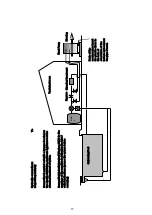
Page 15: ...nd connect the pipe if need Hydraulic connections To respect imperatively Connection is carried out with a by pass located on the circuit of filtration upstream appliances of the chemical treatment of water Connect intake outlet water PVC pipes DN50 to the openings of the machine in following the inlet outlet indications grease the worms before screwing Filte r 15 ...

Page 16: ...or fuse it must protect the Heat pump exclusively the circuit breaker must be specified with curve D the fuse must be specified Am Differential protection 30 mA the length of cable between the connector block of the heat pump and the protection of should not exceed 12 m Control The heat pump is fitted out with a water flow detector which function is to apply the signal to the electronic card when ...

Page 17: ... Pump in these conditions the totality of the water flow goes by the Heat Pump Put into service the Heat Pump in heating mode wait for the indicated pressure being stabilized the correct setting of the pressure is from 21 to 35 kg cm In most of cases pump of filtration given a flow until 9m h you do not have to open the by pass valve If the stabilized pressure is under 21kg cm the progressive open...

Page 18: ...compressor power supply protect the compressor from these extreme conditions the error messages EE 05 occur The condition causing this situation is as follows In heating mode insufficient water flow close the by pass valve for increasing the refrigerant exchange water In cooling mode too important water flow open the by pass valve for decreasing the water flow and so the exchange water refrigerant...

Page 19: ...ms in order to prevent frost damage You should also purge the water if the unit will not work for an extended period of time You should check all parts of the unit thoroughly and completely fill the system with water before turning it on again afterwards 8 2 Troubleshooting guide Improper installation may result in an electrical discharge that could lead to death of or serious injury to pool users...

Page 20: ...uired PP 8 CONDENSER sensor out of order Sensor open or short circuited Check or replace the sensor PP 9 Low ambient temperature protection Ambient temperature is too low or protection temperature setting set too high Check and repair EE 1 High pressure protection Insufficient water flow Check the water flow Pressure switch out of order Replace the pressure switch Have Too much refrigerant gas pre...

Page 21: ...16 9 Electrical diagrams 21 ...

Reviews: