background image

2

11. Only use attachments/accessories specified by the manufacturer.

12.

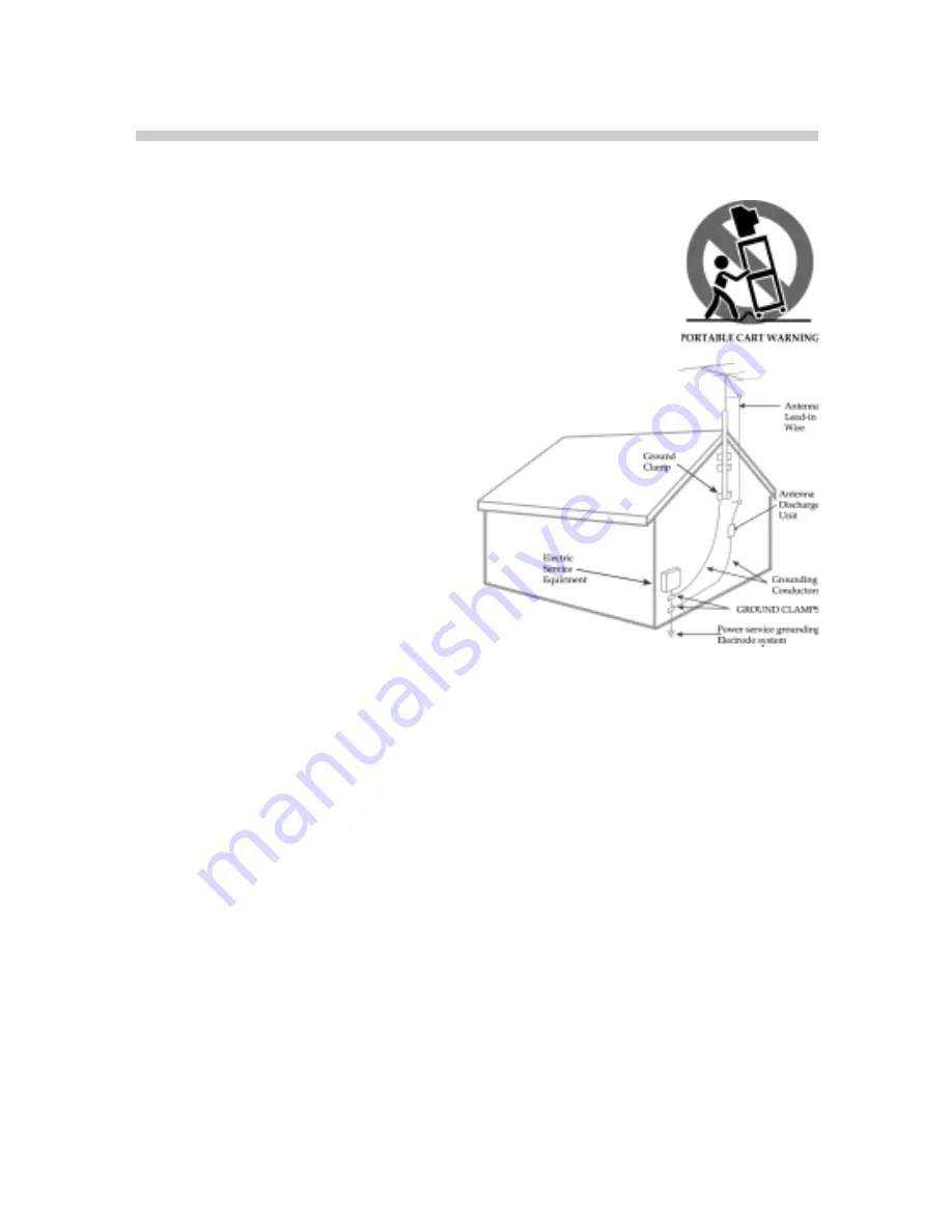
 Use only with the cart, stand, tripod, bracket, or table specified by the

manufacturer, or sold with the apparatus. When a cart is used, use caution when

moving the cart/apparatus combination to avoid injury from top-over.

13. 

Unplug this apparatus during lightning storms or when unused for long periods

of time.

14. Outdoor Antenna Grounding.  

If an outside

antenna or cable system is connected to the

product, be sure the antenna or cable system is

grounded so as to provide some protection against

voltage surges and built-up static charges. Article

810 of the National Electrical Code, ANSI/NFPA

70, provides information with regard to proper

grounding of the mast and supporting structure,

grounding of the lead-in wire to an antenna dis-

charge unit, size of grounding conductors, loca-

tion of antenna-discharge unit, connection to

grounding electrodes, and requirements for the

grounding electrode.

15.Power Lines.

  An outside antenna system should not be located in the vicinity of overhead power lines or

other electric light or power circuits, or where it can fall into such power lines or circuits. When installing an

outside antenna system, extreme care should be taken to keep from touching such power lines or circuits as

contact with them might be fatal.

16. Overloading. 

 Do not overload wall outlets, extension cords, or integral convenience receptacles as this can

result in a risk of fire or electric shock.

17. Servicing. 

 Do not attempt to service this product yourself as opening or removing covers may expose you

to dangerous voltage or other hazards. Refer all servicing to qualified service personnel.

18. Damage Requiring Service.  

Unplug this product from the wall outlet and refer servicing to qualified

service personnel under the following conditions:

h

When the power-supply cord or plug is damaged,

h

If liquid has been spilled, or objects have fallen into the product,

h

If the product has been exposed to rain or water,

h

If the product does not operate normally ,

h

If the product has been dropped or damaged in any way, and

h

When the product exhibits a distinct change in performance–this indicates a need for service.

19. Wall or Ceiling Mounting. 

 The product should be mounted to a wall or ceiling only as recommended by

the manufacturer.

10. Power–Cord Protection.  

Protect the power cord from being walked on or pinched particularly at plugs,

convenience receptacles, and the point where they exit from the apparatus.

Summary of Contents for Dymond DYLT037A

Page 1: ...dinginterferencethatmaycauseundesiredoperation Canada Class B Statement This Class B device meets all requirements of the Canadian interference causing equipment regulations Cet appareil num rique de...

Page 2: ...lines or circuits When installing an outside antenna system extreme care should be taken to keep from touching such power lines or circuits as contact with them might be fatal 16 Overloading Do not o...

Page 3: ...ly approved by the manufacturer who is responsible for compliance with Part 15 FCC rules Note to CATV System Installer This reminder is provided to call the CATV system installer s attention to Articl...

Page 4: ...tee is given to the correctness of the contents Copyright c Copyright 2005 This document contains proprietary information protected by copyright All rights are reserved No part of this manual may be r...

Page 5: ...g the equipment off and on the user is encouraged to try to correct the interference by one or more of the following measures hReorient or relocate the receiving antenna hIncrease the separation betwe...

Page 6: ...e control first 15 Learning how to use your control to operate the memory card reader remote 16 Digital memary card capacity information 17 Icon Description 18 Tuning to off air programs via antenna o...

Page 7: ...rs discoloration scratches and other problems that cannot be repaired may occur Pay attention to the following when handling the screen hDo not use glue or adhesive tape on the screen hDo not write on...

Page 8: ...8 Supplied Accessories The following items come along with your LCD TV...

Page 9: ...and viewing experience to you Your LCD TV has six types of standard video connections You should capitalize on the best connection available from your LCD TV to get the best display quality For exampl...

Page 10: ...10 Connecting to TV Antenna How to Connect Connecting the Additional Speaker...

Page 11: ...ck of your HDTV set top box to the blue Pb Cb jack on the back of your LCD TV 4 Press the Source button of the remote control to display the OSD setup menu to select Component 1 Note 1 If you connect...

Page 12: ...deo under AV2 Input jack 2 Connect the audio red R and white L on the back of camcorder to the audio red R and white L jacks on the back of your LCD TV 3 Connect the yellow video jack on the back of y...

Page 13: ...the OSD set up menu and select RGB 4 You may configure your PC s VGA resolution to output optimized resolution to your LCD TV Connecting to DVI or RGB DVI 1 Connect the DVI connector on your set top b...

Page 14: ...14 Control Functions The control buttons are located beneath the LCD TV Refer to the following table to understand the control button functions...

Page 15: ...always important to read through this section first to learn how to use your remote control especially if you are about to enter the OSD menu to setup the configuration The table below explains each...

Page 16: ...e source menu the software will automatically change some of the remote control buttons to support memory card operation The 37 LCD TV built in photo memory card readers allows you to display your pho...

Page 17: ...17 Digital memory card capacity information...

Page 18: ...18 Icon Description It is recommended that you read through the following icon descriptions These will help to get a quick start and understand the OSD menu...

Page 19: ...the right 5 Follow the instructions in the table below Setting TV Operation 1 Press the MENU button on the remote control to display the main OSD setup menu as pictured below Tuning to off air program...

Page 20: ...of ratings supported by the 37 LCD TV Operation 1 Press MENU from the remote con trol to display the main OSD setup menu 2 Use to navigate the top menu bar and select icon 3 Use to select Content Blo...

Page 21: ...te control to display the main OSD setup menu 2 Use to navigate the top menu bar and select 3 Use to navigate the pull down menu 4 Choose the items you wish to config ure and press the OK button Layou...

Page 22: ...igate the top menu bar and select 3 Use to navigate the pull down menu 4 When selecting the item to change in the pull down menu use buttons to change the parameters This setting configures the viewin...

Page 23: ...option will be used in the event the video sources are from RGB Operation 1 Press the MENU button on the re mote control to display the OSD setup menu 2 Use buttons to navigate the top menu bar and s...

Page 24: ...sound Operation 1 Press the MENU button from the remote control to display the OSD setup menu 2 Use to navigate the top menu bar and select 3 Use to navigate the pull down menu 4 When choosing the ite...

Page 25: ...acklight sleep timer and factory default setting Operation 1 Press the MENU button from the remote control to display the OSD setup menu 2 Use to navigate the top menu bar and select 3 Use to navigate...

Page 26: ...26 Read this section to learn how to maintain and troubleshoot your LCD TV Basic Trouble shooting...

Page 27: ...27...

Page 28: ...shows the frequency ranges supported by the our LCD TV It supports from VGA to XGA If you are connecting your PC to the LCD TV via the RGB port please use the following table in order to setup your PC...

Page 29: ...29 The 37 LCD TV General Specifications...

Page 30: ...ohms color 0 7 Vp p 75 ohms 3 Component input Y Cb Pb Cr Pr 0 7 Vp p 75 ohms excluding SYNC 4 Audio input 400m Vrms 10K ohms 5 S Video output Brightness 1 Vp p 75 ohms color 0 7 Vp p 75 ohms 6 Compon...

Reviews: