Soyer BMK-12 W Operating Instructions Manual Download Page 35

BMK-8 U / BMK-12 W 


35 


6.1.1.3 

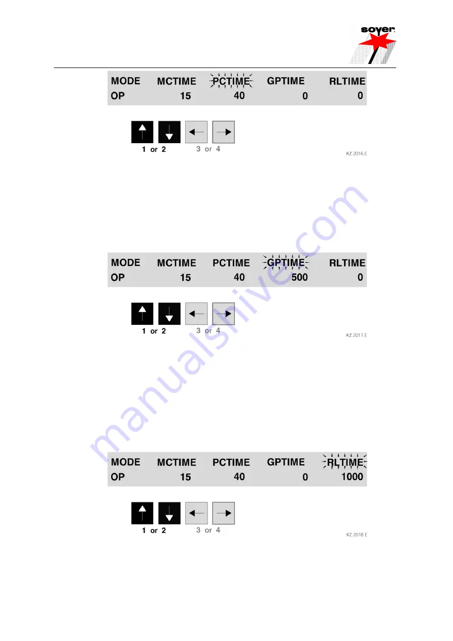
GPTIME (Gas preflow time) 

 
The gas preflow time is the period of time, during which the shielding gas valve is open before starting 
the welding process and remains open after the welding process has been completed. Set value "0" 
when welding without shielding gas. 


• Select function "GPTIME" by pressing either function key "arrow left” 

(3) 

or "arrow right" 

(4)

• Select the corresponding value for the gas preflow time from 0 - 9900 ms in 100 ms-steps by 
pressing function key "arrow up" 

(1) 

or "arrow down" 

(2)


6.1.1.4 

RLTIME (reload time) 

 
The reload time is the period of time the blast air valve requires for transporting the stud from the 
universal feeder to the welding gun or welding head. The longer the blast air hose is, the higher you 
have to set the reload time correspondingly. If automatic reload is not required, set value "0". The 
reload time can only be used in connection with optional "automatic operation" (feeder connection). 
 
• Select function "RLTIME" by pressing either function key "arrow left" 

(3) 

or "arrow right" 

(4)

 
• Select the corresponding value for the reload time from 0 - 9900 ms in 100 ms-steps by either 
pressing function key "arrow up" 

(1) 

or "arrow down" 

(2)


• If you are not satisfied with the welding results, you may change the set welding parameters at any 
time. 


Summary of Contents for BMK-12 W

Page 1: ...Operating Instructions BMK 8 U BMK 12 W Stud Welders...

Page 2: ...BMK 8 U BMK 12 W 2...

Page 3: ...V power supply P01331 BMK 12 W Standard device 3 x 400 V power supply P01332 BMK 12 W automatic Standard device 3 x 400 V power supply and automatic set for stud reload P01333 BMK 12 W universal Speci...

Page 4: ...ed trade mark of Heinz Soyer Bolzenschwei technik GmbH It is prohibited to transmit or reprint this document as well as to utilize or disclose its contents unless this has been expressly granted Non c...

Page 5: ...modification to this machine automatically annuls this declaration Designation of machine Stud welding device Machine type BMK 12W BMK 12W automatic BMK 12W universal BMK 12W universal automatic Machi...

Page 6: ...lding gas 15 3 2 2 Short cycle drawn arc welding with ceramic ferrules 15 3 3 Construction of the BMK 8U BMK 12W stud welders 15 3 4 Technical data 16 3 5 BMK 12 W interfaces 17 3 5 1 CNC interface 17...

Page 7: ...elding operation with ceramic ferrules 39 6 5 1 Instructions for welding with ceramic ferrules 39 7 Quality control 41 7 1 General 41 7 2 Demands on the company 41 7 3 Test execution 41 7 3 1 Producti...

Page 8: ...operated near electronically sensitive life supporting equipment such as in intensive care units in hospitals Persons with pacemakers must neither operate the stud welding equipment nor stay near it...

Page 9: ...h as oil fuel etc must be removed prior to the start of work Electronic equipment e g airbags and the use of explosive substances for fuel supply require further safety precautions when carrying out w...

Page 10: ...may cause damage to the product or to an object surrounding it Instructions for application and other useful information facilitating the proper use of the product Safety symbols The following pictog...

Page 11: ...nsequences Failure of important system functions Failure of prescribed methods for maintenance Danger of persons through electric mechanic thermal and acoustic influences 1 4 Before starting to weld C...

Page 12: ...lication The BMK 8 U BMK 12 W SOYER stud welders for short cycle drawn arc welding allow SOYER threaded studs made of plain steel stainless steel and heat resistant steel as per DIN EN ISO 13918 to be...

Page 13: ...he implementation of these operating instructions CAUTION Do not carry out any actions on the stud welding equipment without specifically knowing the operating instructions or the respective part Ensu...

Page 14: ...also possible to weld nickel and titanium depending on the respective requirements Standard studs for drawn arc and capacitor discharge welding in compliance with DIN EN ISO 13918 can be welded witho...

Page 15: ...ve fillet weld upset formation with a blank metallic surface thus reducing the risk of corrosion and obtaining an improved dynamic behaviour of the welded joint An accurate bulging to scale or in a ca...

Page 16: ...2 A 3P protective earth conductor 3 x 400 V 50 60 Hz standard 3 x 230 3 x 440 3 x 460 3 x 500 or 3 x 600 V 50 60 Hz possible depending on the special type OPTION E constant current 0 3 A phase E const...

Page 17: ...external Terminology SOW Stud on workpiece Shows contact between stud and workpiece Contact is necessary to start welding process via the starting signal Start Contact releases the welding process EP...

Page 18: ...process This state represented as Transformer overheated please wait is shown alternately with the current operation mode on the display Only when this information is no longer shown on the display is...

Page 19: ...tion for welding guns or heads with automatic stud feed 9 Control cable connection 10 Welding cable socket The control cable connection and the welding cable socket serve to connect the stud welding g...

Page 20: ...9 pin connector interface RS 232 OPTION This interface serves to be connected with an external control system 17 Danger sign 18 Type plate 19 Shielding gas connector This connection serves to supply...

Page 21: ...Function key arrow left 6 4 Function key arrow right R Function keys arrow up down Modification of selected parameters flashing symbol in display Function keys arrow left right Selection of parameter...

Page 22: ...set It is possible to set four different operation modes 1 OP Operating state which must be set for normal welding operation 2 PRE Preweld current test 3 LIFT Lift test 4 GAS Gas test MCT Main curren...

Page 23: ...al interface RS232 not yet in use Function key ALTER PARAMETERS Upward alteration of the selected parameters represented blinking in the display Function key ALTER PARAMETERS Downward alteration of th...

Page 24: ...e of the connecting route of both earth clamps This guarantees a current distribution around the stud that is balanced to the largest possible extent and satisfactory welding results Difficult areas a...

Page 25: ...n with sleeve nut Please also refer to the information given in the operating instructions for the welding guns 5 1 8 Mains supply Compare the power data supply voltage current consumption on the type...

Page 26: ...which may be set are also listed in chapter 5 1 3 5 2 2 1 Operating mode OP operating state The operating mode OP allows normal welding operation with the welding parameters set In the case of an exc...

Page 27: ...selected pre current and main current period 5 2 2 3 Operation mode LIFT lift test This operation mode enables you to adjust and check the lift of the gun or welding head For further information pleas...

Page 28: ...If the workpiece is not connected to the earth connection no ground appears on the display Do not activate the release too often in short intervals as this would cause the thermo safety mechanism pro...

Page 29: ...ial functions 5 3 1 Special function Erasing the working storage This special function serves as RESET function e g for eliminating troubles or starting the stud welder the first time All settings of...

Page 30: ...r connected can be set by means of parameter 5 To call this special function please proceed as follows Simultaneously press arrow right and arrow left keys and keep them pressed Switch stud welder on...

Page 31: ...conjunction with a BMK feeder This parameter serves to adjust the post vibration period of the feeder to fill the outlet rail when a stud has been brought in blow off position The after vibration peri...

Page 32: ...n setting feeder type BMS or Display when setting feeder type BMK By using the function keys arrow left or arrow right you can move the slider in the feeder s stud escapement to the left or right end...

Page 33: ...tend the main current at the end of the welding process Depending on the respective welding task this special function allows the weld quality to be improved CAUTION Please observe that the extension...

Page 34: ...so please refer to the standard values indicated in the list Welding parameters 6 1 1 1 MCTIME main current time Select function MCTIME by pressing either function key arrow left 3 or arrow right 4 Se...

Page 35: ...d time The reload time is the period of time the blast air valve requires for transporting the stud from the universal feeder to the welding gun or welding head The longer the blast air hose is the hi...

Page 36: ...0 190 40 40 300 300 RD 10 250 40 40 400 400 Table for BMK 12W ms ms ms M3 5 40 0 M4 RD 6 10 30 40 40 0 300 M5 PD 6 15 50 40 40 0 300 M6 RD 8 30 80 40 40 300 300 M8 PD 8 80 100 40 40 300 300 M10 RD 10...

Page 37: ...The welding process will be started with the parameters set The LED Final contact indicates the end of the welding process Do not move the welding gun or welding head during welding Wait until the we...

Page 38: ...Flow meter Screwing out decreases the flow Connect gas supply hose and gas hose of pressure reducing valve to the stud welder Pressure reducing valve is not included in delivery Open hand wheel item 2...

Page 39: ...ceramic ferrules The measures mentioned in the Start up of stud welder chapter have already been performed 1 Foot plate 2 Ceramic ferrule 3 Welding stud Illustration Stud welding with ceramic ferrule...

Page 40: ...ocess The LED Final contact lights up after completion After completion of the welding process the welding gun or welding head should be held in position for about 5 seconds to allow solidification of...

Page 41: ...lding DVS 0904 Practical information Arc stud welding 7 2 Demands on the company The company must employ a technical supervisor responsible for welding matters as well as qualified operating personnel...

Page 42: ...oor weld quality e g caused by excessive welding energy or insufficient plunge or lift Reduced diameter weld Partial weld Poor weld quality e g caused by insufficient welding energy or humid ceramic f...

Page 43: ...iate tension device until they break If the customer demands that a certain percentage of the welded studs should be tested with a specific test load in production a tension device with load indicator...

Page 44: ...and appropriately qualified personnel are allowed to carry out works at the electric mains supply and welding system NOTE Only use original SOYER spare parts 8 3 Cleaning Cleaning should be carried o...

Page 45: ...lp you eliminate any trouble immediately on the spot If it is difficult or impossible to eliminate the trouble please contact the SOYER customer service responsible for your area or Heinz Soyer Bolzen...

Page 46: ...k for damage Replace if necessary Connecting plug or socket of stud welder is burnt down Have plug or socket replaced by SOYER customer service Both earth cables are not properly connected or not conn...

Page 47: ...d earth clamps for tight fit Stud too loose or not fully inserted into stud holder until stop Insert stud into stud holder until stop Replace stud holder if necessary Magnetic blowing action Arc is fo...

Page 48: ...on again Insufficient mains supply i e supply voltage below value required for welding operation Connect stud welder without extension cable to mains supply If you need to use an extension cable use o...

Page 49: ...OTE Prevent unauthorized use of the stud welding systems by children and unqualified personnel After long system standstill we recommend having the stud welding system checked by SOYER customer servic...

Page 50: ...902 Drawn arc stud welding DVS Information Sheet 0903 Capacitor discharge stud welding with tip ignition DVS Information Sheet 0904 Practical information Arc stud welding EN 14555 Arc welding of metal...

Page 51: ...BMK 8 U BMK 12 W 51 Notes...

Page 52: ...immersion 5 1 5 Adjusting the height of lift 6 2 Start up 7 2 1 Total view 7 2 2 Connecting stud welding gun to stud welder 7 2 3 Operation 7 2 4 Welding parameters 8 3 Spare parts Wear parts 9 3 1 A...

Page 53: ...stud holder with adjusting screw having a length of 73 mm Ensure that the maximum stud length does not exceed 60 mm 1 Stud 3 Lock nut 2 Stud holder 4 Stop screw Different stud holders are required for...

Page 54: ...holder must be screwed on the adapter piece tightly When the screwed connection is not tight enough these parts could be damaged by scorching during the welding process Drawn arc stud holders are esp...

Page 55: ...ding gun with support tube The standard PH 3 stud welding gun uses a gas shroud instead of a support tube 6 The description of installation refers to PH 3 PH 3N and PK 3 stud welding guns 1 Stud holde...

Page 56: ...rt tube When placing the welding gun on the workpiece the stud is pushed back this distance During welding the stud will immerse up to this length into the liquid weld pool on the workpiece The proces...

Page 57: ...stud 3 are lifted from workpiece 1 The lift is adjusted with the help of the adjusting screw 6 located at the back of the welding gun How to adjust the height of lift Insert screwdriver into the groov...

Page 58: ...lding cable into the relevant jack at the stud welder Insert connector of stud welding gun s control cable into the relevant jack at the stud welder Insert gas supply connector of stud welding gun int...

Page 59: ...he operating instructions of your stud welder Before starting your work carry out some experimental welds and test them to find out the optimum adjustment Samples have to be taken during production to...

Page 60: ...hutzgasglocke SGL 2 Aluminium SGL 2 gas shroud aluminium 0 06 F01631 1 Schutzgasglocke Aluminium Gas shroud aluminium SGL 1 0 063 F02477 1 Schutzgasglocke Messing Gas shroud brass SGL 2 0 183 F02476 1...

Page 61: ...erst ck M10 Adapter piece M10 0 025 F02000 FA 2 Massekabel mit Gripzange komplett f r BMK 10 12 Earth cable with locking pliers complete for BMK 10 12 1 426 F01666 FA 2 Massekabel mit Zwinge f r BMK B...

Page 62: ...Keramikringhalter Ceramic ferrule holder 0 013 F03769 KR8 10 Keramikringhalter Ceramic ferrule holder 0 013 F03770 KR12 Keramikringhalter Ceramic ferrule holder 0 018 F02115 1 Stativgrundplatte f r K...

Page 63: ...2 200 mm 0 07 F03166 2 250 mm 0 088 F03781 2 300 mm 0 106 F03782 2 400 mm 0 143 F03717 FA 1 Verl ngerung Pistolenkabel 3 m Extension gun cable 3 m 2 180 F03748 FA 1 Verl ngerung Pistolenkabel 5 m Exte...

Page 64: ...clip white E02858 17 1 Grub screw 8x8 DIN916 18 1 Strain relief F03012 19 1 Bend protection E02854 20 3 m Fabric tube M01390 21 4 Cable fastener 100 25 E02072 22 0 35 m Silicone tube 8x2 0 M01396 23 1...

Page 65: ...head screw M3x20 DIN912 47 1 Acorn nut M4 DIN6797A 48 1 Tooth lock washer M4 DIN6797A 49 1 Fillister head screw M4x8 DIN ISO 7380 50 3 Spring thrust piece M4x10 51 1 Gun label for PH 3N M03596 52 1 S...

Page 66: ...Appendix A REV1 Adjustment of short cycle drawn arc welding guns Appendix A 15 3 5 Illustration of PH 3N stud welding gun main view PH 3N 26 225 002...

Page 67: ...Appendix A Adjustment of short cycle drawn arc welding guns Appendix A 16 3 6 Illustration of PH 3N stud welding gun section of gun body 225 002...

Page 68: ...Heinz Soyer Bolzenschwei technik GmbH Etterschlag Inninger Stra e 14 D 82237 W rthsee Tel 49 0 81 53 8 85 0 Fax 49 0 81 53 80 30 Internet www soyer de E Mail info soyer de...

Reviews: