background image

18

Southworth Products

FPS3000-43NAS Manual

7.  Troubleshooting

Turn off key and disconnect the battery before performing any 

maintenance.

Unit will not lift (motor does not run)

•  Faulty wiring from fuse to lift switch in handle
•  Faulty lift switch
•  Faulty wiring from battery positive terminal to pump contactor to pump motor.
•  Burned out brushes in pump motor
•  Low hydraulic pressure caused by:

•  Pressure relief valve needs adjustment
•  Pump check valve stuck open
•  Faulty solenoid valve

•  Faulty wiring from lift switch to solenoid
•  Faulty lift contactor
•  Defective control circuit fuse
•  Chain or roller bound
•  Check oil level

Forks will not lower

•  Look for binding in chains or rollers

No electrical power

•  Dead Batteries:

•  Keyswitch on “OFF” position
•  E-stop button depressed
•  Loose or dirty battery connections
•  Blown fuse(s)

•  Faulty wiring from fuse to travel control switch
•  Faulty control switch
•  Faulty wiring from travel control switch direction contactor
•  Faulty contactor

Summary of Contents for Stack-N-Go FPS3000-43NAS

Page 1: ...Box 1380 Portland ME 04104 1380 Telephone 800 743 1000 207 878 0700 Fax 207 797 4734 www SouthworthProducts com Model Serial Number __________________________ Date placed in service _________________...

Page 2: ...4 Preparation For Use 12 5 Operation 13 5 1 To Raise and Lower 13 5 2 Travel Function 13 5 3 Turtle Speed Travel 13 5 4 Electric Brake 14 5 5 Reversing Safety 14 5 6 Horn 14 6 Maintenance Repair 14 6...

Page 3: ...w For more information visit www P65Warnings ca gov 11 Drive Wheel Assembly 24 12 Carriage Assembly 25 13 Mast Assembly 26 14 Hydraulic System 27 15 Hydraulic Power Unit 28 16 Hydraulic Schematic 29 1...

Page 4: ...dles when the unit is not powered can lead to damage and or breakage 1 1 Responsibilities of Owner and Users Basic Principles Owners users shall apply sound principles of safety training inspection ma...

Page 5: ...control of the machine conformance with good safety practices is the responsibility of the operator The operator shall make decisions on the use and operation with due consideration for the fact that...

Page 6: ...and access gates or openings shall be secured per the manufacturer s instructions If applicable 2 Distribution of load The load and its distribution on the platform shall be in accordance with the man...

Page 7: ...cordance with OSHA standard 1910 178 29QFR 7 1 06 before being permitted to operate this machine 2 1 Safety Alert Symbols A symbol that indicates a hazard It is composed of an equilateral triangle sur...

Page 8: ...f injury When servicing the unit 1 Key should be in OFF position 2 E stop should be depressed 3 Disconnect the batteries at the terminals Do not perform any repair work on lifts if there is a load on...

Page 9: ...ilers are chocked Travel with the load or forks close to the ground Watch for overhead obstructions Perform all stacker movements smoothly and at a speed that will give you time to react in an emergen...

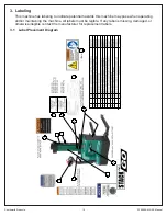
Page 10: ...te potential hazards this machine may pose when operating and or maintaining the machine All labels must be legible If any label is missing damaged or otherwise illegible contact the manufacturer for...

Page 11: ...ired required straddle width dimension 2 inches greater than pallet width 1 on each side of the pallet or load up to a maximum of 50 inches inside width 3 Be sure to fully loosen all bolts before movi...

Page 12: ...g into consideration the center of gravity of the unit If you choose to pick the unit with an overhead hoist use a nylon sling and hoist with a minimum of 2 000 lb capacity The nylon sling will not do...

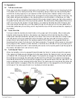
Page 13: ...ards in the forks first direction When rotating the butterfly towards the operator the stacker runs in the reverse direction Always make sure the stacker clears any obstruction when traveling and that...

Page 14: ...r s body the stacker will automatically reverse direction and travel away from the operator When the reversing safety bar comes in contact with your body during operation immediately release your hand...

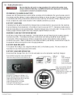
Page 15: ...flame near batteries At temperatures around freezing point battery capacity is reduced by 30 The battery terminals connections and wiring should be clean and free of corrosion When cleaning any of th...

Page 16: ...the brake works correctly Inspect all electrical wiring for loose connections or damage Verify all precautionary labeling is in place and legible 6 3 2 Monthly Maintenance Clean battery terminals and...

Page 17: ...the name plate When you are ordering parts for a cylinder also include the cylinder number This is stamped on the base of the cylinder housing To order replacement parts please call the Parts Departme...

Page 18: ...caused by Pressure relief valve needs adjustment Pump check valve stuck open Faulty solenoid valve Faulty wiring from lift switch to solenoid Faulty lift contactor Defective control circuit fuse Chai...

Page 19: ...2 3 Bearing 4 4 Spindle 2 5 Bolt 4 6 Straddle Leg L H 1 7 Nut 10 8 Bolt 10 9 Bolt 2 10 Seat Fixing 1 11 Drive Wheel Cover 1 12 Rear Cover 1 13 Mast Cover 1 14 Straddle Leg R H 1 15 Bolt 2 16 Battery...

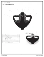
Page 20: ...20 Southworth Products FPS3000 43NAS Manual 9 Control Pod 9 1 August 2018 and Prior...

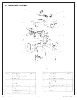
Page 21: ...21 Southworth Products FPS3000 43NAS Manual 9 2 September 2018 to Present...

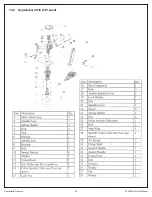
Page 22: ...22 Southworth Products FPS3000 43NAS Manual 10 Steering Assembly 10 1 August 2018 and Prior...

Page 23: ...23 Southworth Products FPS3000 43NAS Manual 10 2 September 2018 to Present...

Page 24: ...Baffle Ring 1 8 Electromagnetic Braker 1 9 Bearing 1 10 Key 2 11 Baffle Ring 1 12 Gear Small 1 13 Screw 4 14 Flange 1 15 Screw 3 16 Bearing 1 17 Seal 1 18 Ring Gear 1 19 Wheel 1 19A Drive Wheel Black...

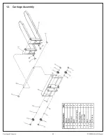
Page 25: ...Products FPS3000 43NAS Manual 12 Carriage Assembly Item Description Qty 1 Block 4 2 Roller 4 3 Washer 4 4 Bolt 4 5 Fixed Pin Chain 1 6 Carriage Assy 1 7 Snap Ring 2 8 Feed Shaft 1 9 Bolt 2 10 Nut 2 1...

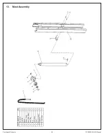
Page 26: ...43NAS Manual 13 Mast Assembly Item Description Qty 1 Chain Assy 1 2 Pivot Pin 1 3 Spacer 2 4 Wheel Chain 1 5 Seat Chain Wheel 1 6 Snap Ring 1 7 Bolt 1 8 Lift Cylinder 1 9 U Bolt 1 10 Mast Assembly 1 1...

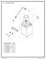
Page 27: ...27 Southworth Products FPS3000 43NAS Manual 14 Hydraulic System HYDRAULIC SYSTEM Item Description Qty 1 Screw 2 2 Washer 2 3 Hydraulic Assy 1 4 L Adaptor 1 5 O Ring 1 6 Oil Hose 1 7 Adaptor 1...

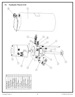
Page 28: ...e 1 1C Unilateral Valve 1 2 Throttle Valve 1 3 DC Hydraulic Valve 1 4A Screw Plug Metal 1 4B Screw Plug Plastic 1 5 Coupling 1 6 HPU DC Motor 1 7 O Ring 1 8 Gear Pump 1 8C Bolt With Spring Wash 2 9 Oi...

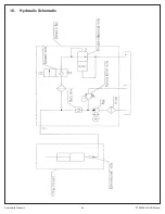
Page 29: ...29 Southworth Products FPS3000 43NAS Manual 16 Hydraulic Schematic...

Page 30: ...30 Southworth Products FPS3000 43NAS Manual 17 Control Panel CONTROL PANEL Item Description Qty 1 Controller 1 2 Fuse 1 3 Travel Contactor 1 4 Lifting Contactor 1...

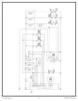
Page 31: ...31 Southworth Products FPS3000 43NAS Manual 18 Electrical Schematic 18 1 Prior to November 2017...

Page 32: ...32 Southworth Products FPS3000 43NAS Manual...

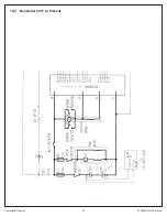
Page 33: ...33 Southworth Products FPS3000 43NAS Manual 18 2 November 2017 to Present...

Page 34: ...34 Southworth Products FPS3000 43NAS Manual...

Page 35: ...9 Battery Connection 12V DC BATTERY 12V DC BATTERY B CHARGER BATTERY CHARGER CONNECTING BATTERY BATTERY CHARGER 120 VAC 24 VOLT SYSTEM 1 NEGATIVE CABLE B POSITIVE CABLE 2 B CABLE BATTERY MAIN POSITIVE...

Page 36: ...California s Proposition 65 Southworth makes no warranty or representation with respect to the compliance of any product with other State or local safety or product standard codes and any failure to...

Page 37: ...tacker loose or broken parts oil dangling wires dents cracked covers etc 6 Check metal frame mast carriage and font load supports for cracked welds worn or flat rollers loose or disconnected chains lo...

Reviews: