7
Operation
On/Off Button
Press the button to turn the meter on. The backlight on the LCD display will turn
off after approx. 2 minutes. To turn the backlight back on, momentarily press the
button. To turn the meter off, press and hold the button until the meter turns off.
V
Ω
Button
Press the V
Ω
button to select voltage, resistance or continuity. When set to
voltage, the meter will automatically select AC or DC voltage. When set to resistance
or continuity, the meter will automatically switch to voltage if the meter is
connected to a live circuit. (> 2.6V).
Autohold/Flashlight Button
Momentarily press the Autohold button to turn the flashlight on and off.
To activate the Autohold function, press and hold the Autohold button until the
“
A HOLD
” indicator appears on the LCD display. When the meter detects a stable
measurement (3 samples with no more than 10% deviation between samples),
the meter will beep once and hold the reading on the LCD display. Additional
Autohold readings can be taken by disconnecting the test leads for at least one
second. The meter will automatically hold a new reading when the leads are
reconnected. Autohold readings will be held for 30 seconds. Afterwards, the meter
will beep twice and exit the Autohold function. To manually exit Autohold, press
and hold the Autohold button until the “
A HOLD
” symbol no longer appears
on the display.
8
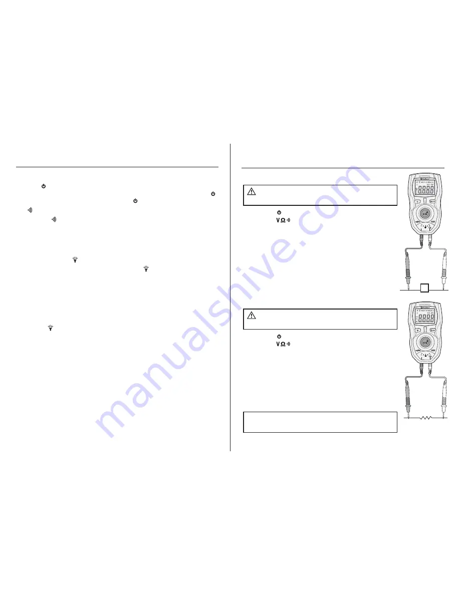
1. Press the button to turn the meter on.
2. Press the button until the “
V
” symbol appears
on the display.
3. Insert the black test lead into the
COM
input jack and
the red test lead into the
V
Ω
input jack.
4. Touch the test lead probes to the circuit under test.
For DC voltage, touch the red teat lead to the positive
side of the circuit and the black test lead to the
negative size.
5. Read the voltage on the LCD display. The meter will
automatically indicate AC or DC voltage.
AC and DC Voltage Measurements
Observe all safety precautions
when working on live voltages.
WARNING:
Operation cont.
V
COM
1. Press the button to turn the meter on.
2. Press the button until the “
Ω
” symbol appears
on the display.
3. Insert the black test lead into the
COM
input jack and
the red test lead into the
V
Ω
input jack.
4. Touch the test lead probes to the component under test.
If the component is installed in a circuit, it is best to
disconnect one side before testing to eliminate
interference with other devices.
5. Read the resistance on the LCD display.
Resistance Measurements
Never test resistance or on a
live circuit.
WARNING:
NOTE:
The meter will automatically switch to voltage if
connected to a live circuit (> 2.6V)
COM
Autoselecting
Multimeter
16030A
CAT IV 600V
COM
Autoselecting
Multimeter
16030A
CAT IV 600V
COM


