6
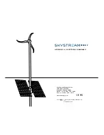
Skystream hybrid 6
TM
Installation Manual, Rev A
Sequence and Overview Of inStallatiOn StepS
Installation of the Pv tracker portion of the Skystream hybrid 6
TM
system
includes the following basic sequence of steps. Please refer to the rel-
evant manual for each step – for example, the tower and hinge plate/gin
pole system has its own installation manual, as does the Skystream 3.7
TM
wind generator.
1. Properly locate/site the Skystream hybrid 6
TM
system. Proper site
selection requires consideration of the system’s access to both clear
flow wind and to un-shaded sun. Other considerations include access
to the site, the wire run path between the system and the electrical
connection point, and safety hazards.
For the Skystream hybrid 6
TM
system to function properly and to its full
potential, the system must be installed in a location with suitable wind
and solar energy potential. wind turbulence sources must be avoided,
as should any potential source of solar shading. Consideration must be
given to both current and future conflicts, such as mature tree height or
future construction plans. Please refer to both the Skystream 3.7
TM
and
the Skystream hybrid 6
TM
Owner’s Manuals for important information.
2. Install an appropriate tower foundation, grounding electrode, and elec-
trical wiring or conduit. Please refer to the appropriate tower and foun-
dation manuals for sizing information and foundation drawings. In most
cases, your local AhJ (Authority having Jurisdiction) will require a “wet
stamped” set of foundation plans. A “wet stamped” plan is reviewed and
stamped, with an original seal, by a PE (Professional Engineer) who
is licensed in your state or province. As they are jurisdiction specific,
Southwest windpower does not provide these “wet stamped” plans but
they can be obtained from Tower Engineering Professionals or a quali-
fied local Pd.
In most cases, a sub-panel must be installed at or near the base of
the tower. The installer should make provisions for this sub-panel in
both the wire/conduit routing and in providing a suitable support for
the sub-panel. From this sub-panel, wiring or conduit must be run in
the shortest practical path to a suitable electrical connection point. In
most cases, this connection point will be the main service panel. In any
event, it should be as close as possible to the point where the electri-
cal system of the supplier and the electrical system of the user are
connected (the location where service voltage is measured, per ANSI
C84.1). Connection of the Skystream hybrid 6
TM
electrical wiring to
any other point (such as an outbuilding’s sub-panel or other remote
panel) requires additional analysis of the entire wire run’s impedance
and, normally, requires increased wire sizes to prevent excessive voltage
rise during system operation. This analysis is the responsibility of the
dealer/installer, using the services of a qualified electrical engineer or
electrician.
3. Assemble the tower, hinge plate and gin pole system, and solar tracker
mounting rings (hereinafter referred to as the tower rings). Please refer
to the appropriate tower manual for instructions regarding the proper
assembly of the tower. A sectional tower which is not properly assem-
bled, using specified compression techniques and forces, may wobble
and cause degraded wind turbine performance.
The center opening in the tower rings is large enough to slide over the
top flange of a completely assembled 45-19 or 45-19hd tower. but,
for convenience, it may be easier to slide them onto the lower sec-
tion of the tower and weld them in place before assembling the upper
sections. A wire pass-through hole must also be drilled in the tower
sidewall and it is normally easier to install that before the tower is
completely assembled. After welding the rings in place, but before the
next step (installing the Skystream 3.7
TM
), the solar tracker top cover
must be slid into position. Refer to the detailed instructions, later in this
manual, for specific information on this process.
4. while the tower is lying down (but properly supported) assemble, install,
and check functionality of the Skystream 3.7
TM
components (including
the Skylevel, cabling, and turbine).
5. Assemble and install the solar tracker drive mechanism, module support
rails, Pv modules, microinverters, and wiring. The solar tracker can be
installed on the tower rings with the tower lying down (but properly sup-
ported) or when standing upright, as preferred by the dealer/installer.
Summary of Contents for Skystream Hybrid 6
Page 2: ......
Page 20: ...20 Skystream Hybrid 6tm Installation Manual Rev A...

