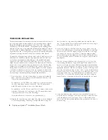
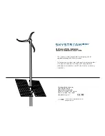
Southwest Windpower Skystream Hybrid 6 Installation Manual Download Page 8

8    

Skystream hybrid 6

TM

 Installation Manual, Rev A

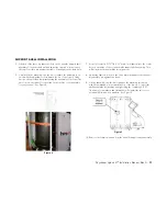
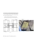
tOwer ring inStallatiOnS

The Skystream hybrid 6

TM

 solar tracker drive unit is mounted to the tower on 

two tower rings, which are tack welded to the tower and which are aligned 
(during the installation process) with the 3 steel rods of the ring welding 
alignment jig – Part # 2-SSh-222.  The alignment jig is a separate dealer-
required item, which is not included with each Skystream hybrid 6

TM

 system 

as it is re-used on multiple installations.  do not attempt to install the tower 
rings without the use of the alignment jig, as the proper spacing and parallel 
alignment of the rings is critical to the proper operation of the system.  
 
Normally, the following steps would take place with the first tower section 
attached to the foundation with the hinge plate and while the first tower 
section is properly supported with cribbing or other suitable and stable 
support. In some cases, the dealer/installer may elect to perform these 
steps on a tower which is in the vertical position (such as a retrofit instal-
lation) or before the tower sections are transported to the site (if welding 
equipment is not available at the installation site).  In such cases, the fol-
lowing instructions may need to be modified slightly to meet the demands 
of the altered installation conditions.  If the tower rings are welded to the 
lower tower section before transportation to the site, it is important to pro-
tect those rings from damage during transport and installation.

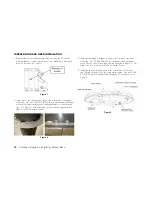
1.  From the bottom of the tower’s base flange, measure up (towards the 

upper end of the tower’s first section) and mark the North side of the 
tower with a permanent marker. 
 
For installation on a 45-19hd tower, with 8-feet of clearance between 
the tower base flange and the lowest point of the Pv array, make a 
mark 154 inches from the bottom of the base flange. 
 
For installation on a 45-19 tower, with 4-feet of clearance between the 
tower base flange and the lowest point of the Pv array, make a mark 
106 inches from the bottom of the base flange. 
 
This mark will be used to locate the wire penetration hole. 

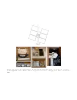
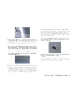
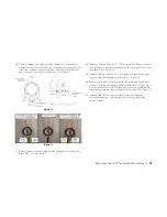
2.  Examine the two tower rings and ensure they have not been damaged 

or bent during shipping or handling.  It is important that the rings are 

flat.  Note that one ring has a larger inside diameter than the other 
ring.  The ring with the larger inside diameter will be the bottom ring, to 
accommodate the tapering of the tower. 

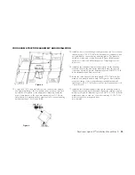
3.  locate the 3 larger holes drilled in the tower rings – these holes are 

used for the welding alignment jig during the installation process. Align 
the three metal rods of the alignment jig between the two tower rings. 
It is easiest to do this one rod at a time.  Using the hardware which 
came with the jig, bolt the alignment rods into place (utilizing the three 
holes you identified earlier) so that the tower rings are properly spaced 
and aligned.

 
4.  Slide the two rings, attached to the alignment jig, over the top of the 

tower making sure that the ring with the larger inside diameter is ori-
ented closest to the tower base.  Push this assembly towards the base 
of the tower until it is snug and the inside of the tower rings are resting 
against the sidewalls of the tower. Check the position of the rings rela-
tive to the hole mark you made in step 1.  The top ring should be about 
6 inches below the hole mark you made.  If necessary, the inside of the 
tower rings can be filed or ground slightly to accommodate an out-of-
round tower or to position the ring assembly so that there is approxi-
mately 6 inches of clearance between the top ring and the hole mark. 

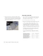
5.  Using a permanent marker, mark the tower sidewalls at every point 

where the inside of the upper and lower tower rings contact the tower 
(on both surfaces of the tower rings).  These contact marks will be 
used to indicate where galvanizing should be ground from the tower to 
permit welding. 

Summary of Contents for Skystream Hybrid 6

Page 1: ...ition The installer is solely responsible for complying with all applicable building and electrical codes To help prevent stainless steel hardware from seizing together 1 apply anti seize lubricant to...

Page 2: ......

Page 3: ..._______________________________________ 11 cross arm structure assembly and installation_______________________ 13 motor gearbox installation_____________________________________________ 14 alignment...

Page 4: ...ackages One pallet contains the shell assemblies and three boxes of hardware The boxes of hard ware are packaged inside of the shell assemblies The second package will be a 6 X 6 x 11 box containing f...

Page 5: ...Hybrid 6tm system 7 Maintain tightness of fasteners according to torque requirements see Maintenance and Inspections Professional installation Southwest Windpower strongly recommends Skystream Hybrid...

Page 6: ...n the shortest practical path to a suitable electrical connection point In most cases this connection point will be the main service panel In any event it should be as close as possible to the point w...

Page 7: ...ower lifting mecha nisms are suitable for raising the tower with the Skystream 3 7tm and the solar tracker installed If the solar tracker is installed on a tower in the upright position appropriate li...

Page 8: ...of the base flange For installation on a 45 19 tower with 4 feet of clearance between the tower base flange and the lowest point of the PV array make a mark 106 inches from the bottom of the base fla...

Page 9: ...is located on the North side of the tower drill a hole for your cord grip or strain relief fitting The diameter of the hole will depend upon the size of your specified electrical cable and your ground...

Page 10: ...unting hardware for each tapered ring See Figure 2 After tightening the four tapered rings should fit flush to each other without gaps 3 Install the remaining four tapered rings to the top side of the...

Page 11: ...e outside of the assembly for easy removal See Figure 4 7 Loosely re insert a 5 16 18 X screw no washers into the center hole on each side of the cross arm side support shell assembly This will help g...

Page 12: ...e tower after tightening If too much play still exists re adjust all rollers the same amount Tighten the jamb nuts once all rollers are adjusted Confirm the shell assemblies roll freely around the tow...

Page 13: ...for Motech 235W solar panels Temporarily leave the bolts loose 15 Install the two solar panel inverter support rails onto the mounting brackets closest to the sun tracker assembly Ensure the rails are...

Page 14: ...perimeter edge lip facing downwards should overlap the top edge of the solar tracker assembly approximately 1 2 inch Alignment and Chain Installation 19 Prior to installing the chain the solar panels...

Page 15: ...rd stop hardware package on the tower gear in the loca tions shown See Figure 12 23 Install the chain around the tower gear and motor sprocket by install ing the master link and attaching the clip See...

Page 16: ...diagram as always however your local AHJ may modify these or may impose additional requirements 1 Using the mounting brackets supplied with the six micro inverters mount them onto the solar panel inve...

Page 17: ...ve compatible Tyco Solarlok connectors The PV module connectors simply plug into the Enphase micro inverter input connectors Install the two WEEBL ground lugs to the rails in the locations shown and r...

Page 18: ...es where appropriate 3 Run a ground cable and an AC cable through the strain relief or fitting to the base of the pole Make connections in the base of the pole A normal new installation will have a su...

Page 19: ...in the OFF position and con nect the motor cable to the connector coming from the control enclo sure Turn the switch to the ON position CAUTION MOTION The controller super capacitors will begin to ch...

Page 20: ...20 Skystream Hybrid 6tm Installation Manual Rev A...

Page 21: ...dpower Inc 1801 West Route 66 Flagstaff Arizona 86001 Phone 1 928 779 9463 Fax 1 928 779 1485 www windenergy com appendix a electrical diagrams January 2012 Southwest Windpower Inc Inc All Rights Rese...

Page 22: ...Installation Manual Rev A Skystream Hybrid 6tm Installation Manual Appendix A Electrical Diagrams 1 Grid Connection Option A 120 240 V 60 Hz Split Phase Sub panel at Tower Base________________________...

Page 23: ...Skystream Hybrid 6tm Installation Manual Rev A 23 Fig 1 Grid Connection Option A 120 240 V 60 Hz Split Phase Sub panel at Tower Base...

Reviews: