background image

8  

Sectional Monopole Tower Foundation & Installation Manual, Revision A

CONSTRUCTING THE FOUNDATION

Foundation Drawings

Detailed technical drawings for the Pier, Mat and SMarT foundations are 
provided in Appendices A, B and C respectively. The drawings are also 
available on Southwest Windpower’s website (www.skystreamenergy.com). 
The drawings were prepared by Tower Engineering Professionals (TEP), 
Raleigh, North Carolina and reviewed and certified by a State of Arizona 
Registered Professional Engineer.

The drawings are provided as a reference to assist with obtaining building 
permits and with the construction approval process. 

Note the foundation dimensions for the Pier and Pad, and Pier founda-
tions will vary based on the Soil Class and Wind Zone. The dimensions 
for the SMarT and Mat foundations do not vary based on soil conditions. 
These foundations assume Soil Class 5 (worst case) conditions exist and 
are sized accordingly. 

Wind Zones

The foundation dimensions are in part dictated by the maximum anticipat-
ed wind speed the turbine will experience. A larger (or deeper) foundation 
is required to withstand higher speed winds. 

The dimensions and construction details for each of the foundations will 
change based on the anticipated wind speed. Refer to the accompanying 
tables to determine your Wind Speed Zone and the location of the foun-
dation dimensions for your tower height and foundation type.

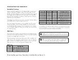
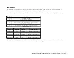
Wind Zones

Zone

Wind Speed

1

120 – 150 mph / 54 – 67 m / sec

2

90 – 120 mph / 40 – 54 m / sec

3

< 90 mph /  40 m / sec

TIP: 

Excellent wind speed information is available on the internet at 

http://www.awea.org/faq/usresource.html as well as other websites.

Tower Height

Foundation Wind Zone

For Dimensions See

33.5 ft (10.2 m)

Mat

1

Appendix A, Sheet S-4A

33.5 ft (10.2 m)

Mat

2

Appendix A, Sheet S-4B

33.5 ft (10.2 m)

Mat

3

Appendix A, Sheet S-4C

33.5 ft (10.2 m)

Pier

1, 2 & 3

Appendix A, Sheets S-5 & S-6

33.5 ft (10.2 m)

SMarT

1, 2 & 3

Appendix C, Sheet S-1

45 ft (13.7 m)

Pier & Pad

1, 2 & 3

Appendix B, Sheet S-5 & S-7

45 ft (13.7 m)

Pier

1, 2 & 3

Appendix B, Sheets S-8 & S-10

45 ft (13.7 m)

SMarT

1, 2 & 3

Appendix C, Sheet S-1

Local building codes may specify the wind speed the foundation must with-
stand. If the building code does not specify a wind speed the local weather 
service can provide maximum wind speed information.

TIP:

 If your installation requires “Wet Stamped” Foundation Drawings 

for your state they may be purchased from Tower Engineering 
Professionals, Raleigh , North Carolina. Phone: 919.661.6351.

Summary of Contents for SkyStream 3.7

Page 1: ...OWER do not manually update scale 1 8 size A CAD file dwg sheet 1 of 1 rev NC DATE APPROVALS DRAWN R D PROD EGR MFG QUAL MATERIAL FINISH DO NOT SCALE DRAWING DWG CAD generated drawing X 1 30 decimals...

Page 2: ...Positioning the Foundations Bolts Pier Mat Foundations _ __11 12 Positioning the Foundations Bolts SMarT Foundation _____ 13 Electrical Conduit_____________________________________ 13 Completing the...

Page 3: ...ction and tower installation 4 Install foundation and tower in accordance with National Electric Code and all local building and zoning codes and requirements 5 Obtain building and construction permit...

Page 4: ...d to construct a foundation for Southwest Windpower s Monopole Towers For the Pier and Mat foundations the information in the manual is sufficient for individuals knowledgeable in working with concret...

Page 5: ...etting into before starting Owners should also be aware that many localities require installation by certified installers or by licensed contrac tors to qualify for clean energy monetary rebates If yo...

Page 6: ...and available open space may require Skystream be installed in a less than optimum location At a minimum try to observe the following general rule for siting the turbine TIP Your dealer can help you...

Page 7: ...the tower over 60 ft 20 m may be required on the other side of the foundation for the vehicle pulling cable and gin pole Slightly less space is required to raise the 33 5 ft 10 2 m tower Refer to the...

Page 8: ...ds The dimensions and construction details for each of the foundations will change based on the anticipated wind speed Refer to the accompanying tables to determine your Wind Speed Zone and the locati...

Page 9: ...andy Gravel and or Gravel 4 Sand Silty Sand Clayey Sand Silty Gravel and Clayey Gravel SW SP SM SC GM and GC 5 Clay Sandy Clay Silty Clay Clayey Silt Silt and Sandy Silt CL ML MH and CH Tower Height F...

Page 10: ...foundation depth In summary consult with a number of contractors and with local building inspectors to achieve the best foundation value Foundation Bolts and Templates Two foundation bolt kits are av...

Page 11: ...the tower to the foundation Using the paper template supplied with the foundation bolt kit as a guide construct a wooden template to position the foundation J bolts 1 2 in 13 mm or 3 4 in 19 mm plywo...

Page 12: ...TEMPLATE IMPORTANT Do not exceed 7 0 0 38 inches 18 0 cm 10 mm dimension or bolts may interfere with hinge plate TOP OF PIER TOP OF ANCHOR BOLT TOP OF WASHER THESE DIMENSIONS MUST BE OBSERVED 7 00 17...

Page 13: ...require direct burial cables be buried to a minimum depth of 24 in 61 cm while cables in conduit may be buried at a depth of 18 in 46 cm Additionally most codes prohibit embedding cables directly in...

Page 14: ...o secure the hinge plate and thread three nuts and washers washer below nut to secure the hinge plate in place Fully tighten the hinge plate to the foundation using the Turn of the Nut method describe...

Page 15: ...be bolted to the hinge plate and foundation and gin pole Perform the following steps to join the tower segments using the gin pole to assist with the process Refer to accompanying figure TOP OF PIER T...

Page 16: ...ole approximately 10 to 20 degrees above horizontal and insert chain links into the slotted plates positioned on either side of the gin pole s central support tube The gin pole should maintain its pos...

Page 17: ...the length of this cable when switching between the 33 5 ft 10 2 m and 45 ft 13 7 m towers or because of variations in the location of the lifting tab Refer to the accompanying Adjusting Cable Length...

Page 18: ...ower by slowly driving the lifting vehicle away from the tower to take the slack out of the cable keep the vehicle in line with the tower avoid loading the tower in a lateral direction The vehicle sho...

Page 19: ...tion section of this manual Observe the recommended bolt tightening procedure Connect the gin pole to the lifting tab at the mid section of the tower using the wire rope cable and shackles provide wit...

Page 20: ...ystream on calm days If the wind turbine seems to favor a single position with no wind the tower may require fine tuning even if it appears level using the bubble leveling technique To fine tune the t...

Reviews:

Related manuals for SkyStream 3.7