background image

20  

Sectional Monopole Tower Foundation & Installation Manual, Revision A

Leveling the Tower

Leveling the tower is most easily accomplished using only four of the eight foundation bolts. Once the tower is leveled the remaining bolts can be fully 
tightened to secure the tower.

Be aware that leveling the tower may require some trial and error adjustments – even though the base is level, the upper tower flange may be off level 
due to manufacturing tolerances. 

To level the tower:

•   Level the tower on a calm day to minimize movement of Skystream. Start by loosening all the upper foundation nuts about a full turn. 

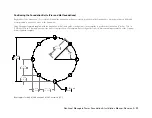
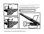
•   Loosen and lower the four nuts on the “sides” of the foundation base plate. In other words the tower should be supported by the four “corner” nuts of 

the tower base plate. (refer to 

Fig. 8

, Bolts A and B are “corner” bolts)

•   Using two bubble levels set perpendicular to each other on the base plate adjust the foundation nuts until the tower is level. Magnetic bubble levels 

may make this process easier. 

•   Once the tower is level tighten all nuts and recheck level.

Observe the position of Skystream on calm days. If the wind turbine seems to favor a single position with no wind, the tower may require fine tuning even 
if it appears level using the bubble leveling technique.

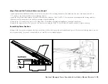
To fine tune the tower realize that the nose cone of the wind turbine will “point” in the direction of the tower low side. Therefore, to level the tower, slightly 
raise the side of the tower under the nose cone or lower the side of the tower opposite the nose cone. Make fine adjustments.  Approximately one turn of 
a foundation nut equates to slightly more than 1/8 in (3.2 mm) so even a half turn adjustment will make a difference. 

Tightening Foundation bolts

Tighten the foundation bolts by using the Turn of the Nut Method as described below.

Turn of the Nut Method of Tightening

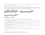
•  First tighten each nut to a “snug tight” condition to bring the hinge plate in full contact 
   with the foundation. “Snug Tight” is defined as the tightness attained by a “few” impacts 
   of an impact wrench or the full effort of a man using an ordinary spud wrench.

•  Following the initial snug tightening, tighten each nut an additional 1/3 to 2/3 turn.

WARNING: 

Never leave foundation bolts loose. 

Foundation bolts may be temporarily loosened during 
tower leveling – however, never leave tower unless 
ALL foundation bolts are FULLY tightened.

Summary of Contents for SkyStream 3.7

Page 1: ...OWER do not manually update scale 1 8 size A CAD file dwg sheet 1 of 1 rev NC DATE APPROVALS DRAWN R D PROD EGR MFG QUAL MATERIAL FINISH DO NOT SCALE DRAWING DWG CAD generated drawing X 1 30 decimals...

Page 2: ...Positioning the Foundations Bolts Pier Mat Foundations _ __11 12 Positioning the Foundations Bolts SMarT Foundation _____ 13 Electrical Conduit_____________________________________ 13 Completing the...

Page 3: ...ction and tower installation 4 Install foundation and tower in accordance with National Electric Code and all local building and zoning codes and requirements 5 Obtain building and construction permit...

Page 4: ...d to construct a foundation for Southwest Windpower s Monopole Towers For the Pier and Mat foundations the information in the manual is sufficient for individuals knowledgeable in working with concret...

Page 5: ...etting into before starting Owners should also be aware that many localities require installation by certified installers or by licensed contrac tors to qualify for clean energy monetary rebates If yo...

Page 6: ...and available open space may require Skystream be installed in a less than optimum location At a minimum try to observe the following general rule for siting the turbine TIP Your dealer can help you...

Page 7: ...the tower over 60 ft 20 m may be required on the other side of the foundation for the vehicle pulling cable and gin pole Slightly less space is required to raise the 33 5 ft 10 2 m tower Refer to the...

Page 8: ...ds The dimensions and construction details for each of the foundations will change based on the anticipated wind speed Refer to the accompanying tables to determine your Wind Speed Zone and the locati...

Page 9: ...andy Gravel and or Gravel 4 Sand Silty Sand Clayey Sand Silty Gravel and Clayey Gravel SW SP SM SC GM and GC 5 Clay Sandy Clay Silty Clay Clayey Silt Silt and Sandy Silt CL ML MH and CH Tower Height F...

Page 10: ...foundation depth In summary consult with a number of contractors and with local building inspectors to achieve the best foundation value Foundation Bolts and Templates Two foundation bolt kits are av...

Page 11: ...the tower to the foundation Using the paper template supplied with the foundation bolt kit as a guide construct a wooden template to position the foundation J bolts 1 2 in 13 mm or 3 4 in 19 mm plywo...

Page 12: ...TEMPLATE IMPORTANT Do not exceed 7 0 0 38 inches 18 0 cm 10 mm dimension or bolts may interfere with hinge plate TOP OF PIER TOP OF ANCHOR BOLT TOP OF WASHER THESE DIMENSIONS MUST BE OBSERVED 7 00 17...

Page 13: ...require direct burial cables be buried to a minimum depth of 24 in 61 cm while cables in conduit may be buried at a depth of 18 in 46 cm Additionally most codes prohibit embedding cables directly in...

Page 14: ...o secure the hinge plate and thread three nuts and washers washer below nut to secure the hinge plate in place Fully tighten the hinge plate to the foundation using the Turn of the Nut method describe...

Page 15: ...be bolted to the hinge plate and foundation and gin pole Perform the following steps to join the tower segments using the gin pole to assist with the process Refer to accompanying figure TOP OF PIER T...

Page 16: ...ole approximately 10 to 20 degrees above horizontal and insert chain links into the slotted plates positioned on either side of the gin pole s central support tube The gin pole should maintain its pos...

Page 17: ...the length of this cable when switching between the 33 5 ft 10 2 m and 45 ft 13 7 m towers or because of variations in the location of the lifting tab Refer to the accompanying Adjusting Cable Length...

Page 18: ...ower by slowly driving the lifting vehicle away from the tower to take the slack out of the cable keep the vehicle in line with the tower avoid loading the tower in a lateral direction The vehicle sho...

Page 19: ...tion section of this manual Observe the recommended bolt tightening procedure Connect the gin pole to the lifting tab at the mid section of the tower using the wire rope cable and shackles provide wit...

Page 20: ...ystream on calm days If the wind turbine seems to favor a single position with no wind the tower may require fine tuning even if it appears level using the bubble leveling technique To fine tune the t...

Reviews: