background image

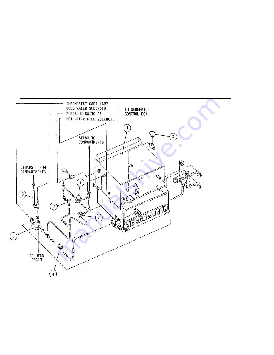
PARTS LIST 

SECTION 7:                                                                                 


MODELS: GC-2 & GC-3 

GDA-2 & GHD-2 

GENERATOR  ASSEMBLY


FIG. 9 


33 

Summary of Contents for CQ-325S

Page 1: ...and or electrical cooking equipment then the terms and conditions of the Manufacturer s Limited Warranty will be rendered void and no warranty of any kind shall apply If the equipment has been changed altered modified or repaired by other than a qualified service technician during or after the 12 month limited warranty period then the manufacturer shall not be liable for any incidental or conseque...

Page 2: ...nstructions 15 SECTION SIX SERVICE Service Information 16 SECTION SEVEN PARTS Parts List 23 SECTION EIGHT WIRING Wiring Diagrams 37 CAUTION WATER QUALITY IS THE MAJOR FACTOR AFFECTING THE PERFORMANCE OF YOUR APPLIANCE INCOMING WATER HARDNESS SHOULD NOT EXCEED 2 0 PPM GRAINS AND THE pH SHOULD NOT EXCEED 7 5 IF YOU ARE UNSURE OF WATER CONDITIONS HAVE IT ANALYZED CONSULT YOUR LOCAL WATER DEPARTMENT O...

Page 3: ... not be liable for consequential or special damages of any nature that may arise in connection with such product or part Should service be required at times which normally involve overtime or premium labor rates the owner shall be charged for the difference between normal service rates and such premium rates In all circumstances a maximum of one hundred miles in travel and two and one half hours 2...

Page 4: ... must be installed in supply piping convenient and adjacent to appliance EC Unless otherwise specified Field Wire Electrical Connection to be 120 Volts 60 Hertz single phase with grounding wire DR Appliance drain is 2 pipe size Provide open air gap type drain CW Cold Water supply to Boiler Provide 3 8 copper tube A Backflow Prevention Device acceptable to BOCA Code or equivalent must be installed ...

Page 5: ...to right and front to back Appliance should be elevated on the right 1 16 to 1 8 to assure proper compartment drainage Bolt and anchor appliance securely to the floor Seal bolts and flanged feet with Silastic or equivalent compound SERVICE CONNECTIONS Make service connections as indicated in LEGEND Fig 1 GAS INSTALLATION TO CONFORM TO LOCAL CODES OR IN THE ABSENCE OF LOCAL CODES TO NATIONAL FUEL G...

Page 6: ...ck to O The buzzer will now be audible and must be silenced by releasing Operating handle Check each compartment in a similar manner Close compartment door and turn Handwheel clockwise sufficiently to provide a good seal on door gasket Dial Timer to 5 minutes Pull out Operating Handle and set in position Steam entry into compartment will be audible and Compartment Vent located at rear left side of...

Page 7: ...team reduced to maximum 6 psi pressure by the Pressure Regulating Valve will then be permitted to enter the compartment but not exit Air captured in the sealed compartment is allowed to exhaust through the Compartment Vent which will close at approximately 180 F whence the compartment becomes an entirely sealed chamber The duration of the cooking cycle is controlled by the Timer and when desired t...

Page 8: ...e pans since steam circulation between pans in the compartment will be impeded Always preheat compartments for satisfactory results When a11 compartments are to be used at the same time allow one compartment to recover steam pressure approx 4 1 2 p s i before commencing cooking operation on next compartment When time does not allow for defrosting of frozen vegetables such as loose pack peas corn d...

Page 9: ...Shell Solid 7 8 4 6 Eggs in 2 1 2 2 3 3 dozen 1 3 Shell Perforated 4 6 4 6 Fish Fillets 2 1 2 8 12 3 1 3 Perforated 10 15 4 6 Meatloaf 2 1 2 35 40 15 1 3 Solid for Broth 40 45 4 6 Peas 2 1 2 6 7 5 1 3 Perforated 8 9 4 6 Potatoes cut 2 1 2 20 25 10 1 3 Regular Perforated 25 30 4 6 Potatoes cut 2 1 2 15 18 10 1 3 French Fry Perforated 18 20 4 6 Spinach 4 3 5 3 1 2 cut cleaned Perforated 4 6 3 4 Rice...

Page 10: ...PERIODIC MAINTENANCE SECTION 4 MODELS GC 2 GC 3 FIG 2 SIDE VIEW 8 ...

Page 11: ...uld read 0 during shut down and function in a range of approximately 9 to 13 p s i during operation of the appliance Item E The Water Level Control is a mechanical switch intended to maintain proper water level in the Boiler A Float is contained within the chamber of the Water Level Control and when it drops it will trip the switch in the control and demand sufficient water to replenish it to the ...

Page 12: ...Control Box is plumbed to sense the pressure in the Boiler and thence control the operating cycle of the Gas Combination Control Valve Item I This switch is factory set to energize the Gas Combination Control Valve and ignite the Main Burners at 9 psi but to de energize the Valve and turn off Burners at 11 psi thus maintaining a pressure range in the Boiler between 9 psi to approximately 13 psi ov...

Page 13: ...d from condensed steam to exhaust into the appliance Drain but will retain steam being of a higher temperature Item T Drain for compartments and Boiler approximately 2 pipe size Must be provided with open air gap type floor drain Item U Thermostat Capillary Bulb fastened to appliance Drain Refer to Item P Item V Override Solenoid Valve functions only briefly at initial Start Up of Boiler and is co...

Page 14: ...PERIODIC MAINTENANCE SECTION 4 MODELS 6C 2 GC 3 FIG 3 12 EXHAUST TO DRAIN STEAM IN ...

Page 15: ...PARTMENT DOOR SHOULD BE LUBRICATED ONCE A MONTH TO GAIN ACCESS TO SCREW OPEN COMPARTMENT DOOR AND TURN HANDWHEEL CLOCKWISE CLOSE DIRECTION UNTIL GASKET RETAINING PLATE IS FULLY EXTENDED OUT OF DOOR GRASP FINGER HOOKS AND LIFT UP AND OUT TO REMOVE GASKET PLATE ASSEMBLY APPLY GREASE NLG12 CONSISTENCY OF 285W60 VISCOSITY LIBERALLY TO THRUST SCREW ROTATING HANDWHEEL TO ASSURE COMPLETE COVERAGE REPLACE...

Page 16: ...cumulation is evident IF PARTICULARLY GREASY FOODS HAVE BEEN COOKED IN THE COMPARTMENT DEPOSITS MAY ACCUMULATE IN EXHAUST VALVES AND MUST BE REMOVED BY CLOSING DOOR SEALING COMPARTMENT SETTING TIMER AND AT FREQUENT INTERVALS PULL OUT AND RELEASE OPERATING HANDLE TO BLOW STEAM THROUGH VALVE AND DISSOLVE GREASE Item H A Pressure Gauge is fastened to the bottom face of the Cooker Control Panel It is ...

Page 17: ...erating Handle and set in position Pilot light will indicate that cooking cycle is now in progress Completion of the cooking cycle is indicated by the buzzer going on and the pilot light off Set Operating Handle back and turn Handwheel fully counter clockwise Open door and remove food in pans CLEANING At the end of each day turn appliance OFF Remove pans and side racks from compartments Remove foo...

Page 18: ...o turn Foreign matter or lack of lubricant on dry Thrust Screw may cause threads to bind Refer to Section 4 Periodic Maintenance If Thrust Screw is bent or threads are badly worn remove Thrust Screw and replace Refer to Steamer Compartment Door Assembly Section 7 Page 23 Door Gasket is leaking Gasket Retainer Cap Screws may be loose and must be tightened to prevent steam leakage Gasket may be nick...

Page 19: ...ve may be incapable of opening Since this valve contains a moveable blade and when de energized the blade reacts as a guillotine which should be free to move fully down into the valve pocket projection at bottom of valve so that the pierced hole in the blade aligns perfectly with the body opening If debris has accumulated in the bottom of the valve pocket then blade obviously will be impeded from ...

Page 20: ...inet is ON and steam pressure reading shows 5 to 6 p s i on Pressure Gauge of Cooker Control Panel and all compartments fail to function for the cooking cycle then power obviously is not being supplied to Cooker and wiring must be checked The magnetic coil of the Steam Solenoid Valve may be defective and require replacement With Compartment Door open observe if steam enters compartment when an out...

Page 21: ...he float is unable to trip the switch in the control to de energize the solenoid valve and consequently stop water from being fed to the Boiler and flooding the system Refer to Boiler on Removal of Sealants etc This malfunction is extremely serious and indicates that water quality is inadequate and must be rectified immediately with a proper water conditioner Pressure Relief Valve leaks or opens f...

Page 22: ... Each nut should be turned slightly and the pressure reading on the Gauge observed before adjusting the next nut unnecessarily Water is not being supplied to Boiler When the appliance is first turned ON and assuming that water supply is definitely available to the appliance and after 20 minutes no water can be observed in the Water Gauge Assembly then either the Solenoid Hot Water Valve is defecti...

Page 23: ...ssembly Examine interior of Boiler for sealant and or lime build up If considerable sealant is evident then the Boiler Blow down Valve similar to Exhaust Solenoid Valve must also be examined Refer to page 17 on cleaning procedure Removal of sealants Disconnect all 3 union pipe fittings and hot water tilt connection to Boiler Cap and seal all 4 opened connections to Boiler Plumbed directly to the B...

Page 24: ... 1 4 OD that it has no severe kinks Remove tube and check that free flow of gas is possible through it Also if the orifice of the Pilot Burner is slightly plugged gas flow will be impeded causing an irregular flame and will require replacement Main Burners refuse to ignite Assuming that the Pilot Burner flame is of proper size and envelops the thermocouple tip but the Main Burners refuse on demand...

Page 25: ...PARTS LIST SECTION 7 COMPARTMENT DOOR ASSEMBLY FIG 4 23 ...

Page 26: ...ment parts may be ordered either through a Southbend Authorized Parts Distributor or a South bend Authorized Service Agency When ordering parts please supply the Model Number Serial Number Part Number Description plus Finish Type of Gas and Electrical Characteristics as applicable For parts not listed consult a Southbend Authorized Parts Distributor or Southbend Authorized Service Agency If necess...

Page 27: ...8 8 1181 Alignment Screw 2 9 1 69CO Nut 2 10 8 1182 Thrust Bar 1 11 8 1183 Thrust Screw 1 12 2 W1B6 Washer 1 13 8 1184 Compartment Door 1 14 8 1187 Bronze Bushing 2 15 1 T6S8 Tension Pin 2 16 8 1188 Hinge 2 17 8 1189 Hinge Pin 2 18 2 011R 0 Ring 6 19 1 65S4 Hinge Screw 6 20 8 1190 Aluminum Bushing 1 21 8 1191 Handwheel 1 22 2 W9S8 Hasher 1 23 8 1193 Open Close Label 1 24 1 65S6 Handwheel Screw 1 2...

Page 28: ...PARTS LIST SECTION 7 COOKER ASSEMBLY FIG 5 25 ...

Page 29: ...M633 Microswitch 2 12 1 S7C5 Miroswitch Spacer 2 13 2 M3C9 Microswitch Screw 2 14 3 CV42 Compartment Vent 1 15 3 S467 Exhaust Solenoid Valve 1 16 3 22DO Brass Nipple 2 17 3 U4BE Union Elbow 2 18 3 S422 Steam Solenoid Valve 1 REQUIRED FOR EACH COOKER 19 3 68BC Connector to Pressure Gauge Tube 1 20 8 1226 Steam Header 2 Comp 1 or 8 1227 Steam Header 3 Comp 1 21 8 1228 Exhaust Header 2 Comp 1 or 8 12...

Page 30: ...PARTS LIST SECTION 7 COOKER CONTROLS FIG 6 27 ...

Page 31: ...Instruction Label 2 comp 1 or 8 1205 Cooker Instruction Label 3 comp 1 7 3 PG15 Pressure Gauge 1 8 3 15PG Gauge Fastening Bracket 2 9 1 39CO Pressure Gauge Nut 2 10 1 59CO Enclosure Fastening Nut 2 comp 8 or Enclosure Fastening Nut 3 comp 9 11 4 BU09 Buzzer 1 12 8 1207 Cooker Control Enclosure 2 comp 1 or 8 1208 Cooker Control Enclosure 3 comp 1 13 8 1211 Cooker Enclosure Cover 2 comp 1 or 8 1212 ...

Page 32: ...PARTS LIST MODELS GC 2 GC 3 SECTION 7 CABINET FIG 7 29 ...

Page 33: ...ot Rear 2 4 5 FS64 Adjustable Foot Insert Front 2 5 5 MC02 Magnetic Door Catch 2 1 11C2 Magnetic Door Catch Screws 8 6 8 1303 Right Hand Door Shown 1 8 1304 Left Hand Door 1 7 8 1414 Flue Stack 2 Compartment or 1 8 1415 Flue Stack 3 Compartment 1 8 8 1416 Stack Cover 2 compartment or 1 8 1417 Stack Cover 3 compartment 1 Note Item No 3 Flanged Adjustable Foot may be specified as an option on all fo...

Page 34: ...PARTS LIST SECTION 7 MODELS GC 2 GC 3 GENERATOR CONTROL BOX ASSEMBLY FIG 8 31 OVERRIDE ...

Page 35: ... Thermostat Screw 2 3 4 70EU Ground Terminal 1 4 4 LQE7 Liquid Tite Elbow Assembly 3 5 8 1244 Control Box Cover 1 6 1 33C3 Cover Bolts 4 7 3 S162 Solenoid Valve 2 8 1 23C3 Terminal Block Screw 4 9 4 22T8 Terminal Block 2 10 4 S191 Power Switch 1 11 4 PL04 Pilot Light 1 12 3 PA26 Pressure Switch c w 3 RD20 Transducer 2 13 1 55C8 Pressure Switch Bolt 8 32 ...

Page 36: ...PARTS LIST SECTION 7 MODELS GC 2 GC 3 GDA 2 GHD 2 GENERATOR ASSEMBLY FIG 9 33 ...

Page 37: ...NTITY 1 8 1800 Gas Boiler 1 2 3 SRV3 Boiler Safety Valve 1 3 Override Solenoid Valve 1 4 3 S567 Blow down Solenoid Valve 1 or 3 BVEO Manual Valve 1 5 8 1254 Appliance Drain Assembly 1 6 8 1255 Exhaust Drain Assembly 1 7 3 TST1 Thermostatic Steam Trap 1 8 3 PR52 Pressure Regulator 1 34 SECTION 7 ...

Page 38: ...PARTS LIST FIG 10 35 SECTION 7 MODELS GC 2 GC 3 GDA 2 GDH 2 GAS BOILER ASSEMBLY BOILER RATED 250 000 BTU HR ...

Page 39: ...3 8 1408 Handhole Cover Plate 1 4 2 75U9 Fastening Bolt 1 5 8 1409 Handhole Gasket 1 6 8 1410 Yoke 1 7 2 75U0 Fastening Nut 1 8 9 1401 Hood and Spud 6 9 8 1404 Gas Manifold 1 10 6 36TB Thermocouple with Bulb 1 n 6 36C0 Gas Combination Control Valve 1 12 6 36PB Pilot Burner Assembly 1 13 8 1406 Burner 5 8 1407 Burner with bracket for pilot 1 36 ...

Page 40: ...WIRING DIAGRAM 37 SECTION 8 MODELS GC 2 GC 3 ...

Page 41: ...WIRING DIAGRAM SECTION 8 MODEL GDA 2 38 ...

Page 42: ...WIRING DIAGRAM 39 SECTION 8 MODEL GHD 2 ...

Page 43: ...WIRING DIAGRAM MODELS EDA 2 SCDA 2 GDA 2 DDA 2 SECTION 9 SUPPLEMENT ...

Page 44: ...T NO DESCRIPTION QUANTITY A 4 S001 Pressure Option Switch 1 B 8 1275 Formed 5 Brass Tube 1 C 8 1274 Steam Diverter Assembly Not Visible 1 D 3 S322 OJfcfc Steam Solenoid Valve 1 Replaces Steam Solenoid Valve 3 S422 E 8 1206 Instruction Panel 1 SUPPLEMENT SECTION 9 ...

Page 45: ...fessional service may be necessary to extend the useful life of this unit When service is needed contact a Southbend Authorized Service Agency or your dealer To avoid confusion always refer to the model number serial number and type of your unit southbend 1100 Old Honeycutt Road Fuq Fuquay Varina NC 27526 919 552 9161 FAX 919 552 9798 800 348 2558 PART NUMBER A44 00014 A MIDDLEBY COMPANY ...

Reviews: