


1 - 25
Master Section
1 - AUX MASTERS
Each of the six AUX outputs has a master output level control and
associated AFL switch.
AUX AFLs
Just as the Channel PFL switches allow pre-fade listening, so you can
monitor each AUX output after the level control by pressing the AFL
switch. This routes the AUX output signal to the MONITOR or PHONES,
replacing any existing signal which is selected. The METERS also switch
from the selected source to display the PFL/AFL signal and the PFL/
AFL LED lights to warn that a PFL or AFL switch is pressed. When you
release the switch the Monitor swaps back to the previous source.
2 - POWER INDICATORS
These LEDs light to show that power is connected to the console and
that the internal power supply is operating correctly.
3 - BARGRAPH METERS
3-colour peak reading BARGRAPH METERS are provided to monitor
the four Subgroup outputs and the selected M Phones source
(2TK, C (mono), Mix or Groups), giving you a constant warning of
excessive peaks in the signal which might cause overloading. Aim to
keep the signal within the amber segments at peak levels for best
performance.
Similarly, if the output level is too low and hardly registering at all on
the meters, the level of background noise may become significant.
Take care to set up the input levels for best performance.
When any PFL or AFL switch is pressed, the L & R meters automatically
switch to show the selected PFL/AFL signal on both meters, in mono.
4 - MIX
Pressing the Mix switch routes the post-fade Subgroup signals in pairs
to the main Mix. Groups 1 & 3 are routed to Mix L, Groups 2 & 4 are
routed to Mix R.
5 - MASTER FADERS
The MASTER FADERS set the final level of the Subgroup and Mix L & R
outputs. These should normally be set close to the `0 mark if the
input GAIN settings have been correctly set, to give maximum travel on
the faders for smoothest control.
6 - MIX TO C (mono)
Pressing this switch routes the post-fade Mix L/R outputs to the C
(mono) bus to create a separate mono mix to feed, for example, an
induction loop or centre cluster. Note: If there are input channels
which are routed both to Mix and C (mono), pressing this switch will
have an additive effect which may lead to feedback.
7 - PHONES
The PHONES output appears on a 3-pole 1/4 jack, suitable for
headphones with an impedance of 200
W
or higher.
Summary of Contents for LX7-2
Page 1: ...i T T T T Technical Manual echnical Manual echnical Manual echnical Manual echnical Manual ...
Page 5: ...1 1 INTRODUCTION ...
Page 8: ...1 4 ...
Page 18: ...1 14 Audio Connector Pinouts ...
Page 19: ...1 15 Dimensions ...
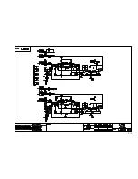
Page 20: ...1 16 BLOCK DIAGRAM ...
Page 21: ...1 17 ...
Page 22: ...1 18 USING THE CONSOLE ...
Page 23: ...1 19 Overview A 16 channel frame is shown ...
Page 34: ...2 2 ...
Page 35: ...2 3 ...
Page 36: ...2 4 ...
Page 37: ...2 5 ...
Page 38: ...2 6 ...
Page 39: ...2 7 ...
Page 40: ...2 8 ...
Page 41: ...2 9 ...
Page 42: ...2 10 ...
Page 43: ...2 11 ...
Page 44: ...2 12 ...
Page 45: ...2 13 ...
Page 46: ...2 14 ...
Page 47: ...2 15 ...
Page 48: ...2 16 ...
Page 49: ...2 17 ...
Page 50: ...2 18 ...
Page 51: ...2 19 ...
Page 52: ...2 20 ...
Page 53: ...2 21 ...
Page 54: ...2 22 ...
Page 55: ...2 23 ...
Page 56: ...2 24 ...
Page 57: ...2 25 ...
Page 58: ...2 26 ...
Page 59: ...2 27 ...
Page 60: ...2 28 ...
Page 61: ...2 29 ...
Page 62: ...2 30 ...
Page 63: ...LX7 II Spare Parts Page 3 1 LX7 II Spare Parts ...
Page 108: ...Page 3 46 LX7 II Spare Parts ...


