background image


4

Introduction 

The PowerSwap is a versatile accessory for electric musicians offering the ability to swap a single amp head power signal between 
two speaker cabinets.  The PowerSwap inserts between the amplifier speaker connection and the speaker cabinets to be 
swapped. 
 
The PowerSwap can be controlled 3 ways. 


Via MIDI using pre-assigned Program Change commands. 


Via MIDI using pre-assigned Control Change commands. 


Via a push/push or momentary style mechanical footswitch. 

 
The PowerSwap incorporates a high quality double pole relay to swap both the ground and signal connections of the speakers.  
Up to 1000 watts of audio signal can be swapped using the PowerSwap. 

Panel Features 

The back panel of the PowerSwap has a MIDI IN jack, a MIDI THRU jack, and power connector.  The front panel has three mono 
(tip-ring) ¼” jacks labeled “A”,  “B” and “COM” and 2 indicators.  The “PWR” indicator illuminates whenever power is applied to the 
unit.  The “B” indicator illuminates whenever the relay is activated to connect the “B” and “COM” circuits together. 

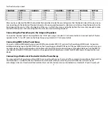
Setting the PowerSwap MIDI Channel 

The PowerSwap is factory set to MIDI channel 16.  If this is an acceptable MIDI channel for your use than you do not need to do 
anything more.  If you wish to set the unit to respond to another MIDI channel, then you will need to change the switch setting 
inside the unit.  
 
To access the switch use a Phillip’s head screwdriver to remove the 2 screws on the front panel.  Slide the insides partially out by 
pulling the front panel away from the case.  Inside you will find a 4 position switch that can be used to set the channel.  If the 
switch is turned on then this indicates a “1” otherwise it indicates a “0”.  Use the following chart to determine the switch setting 

Summary of Contents for PowerSwap

Page 1: ...PowerSwap 1000 Watt Musical Instrument Speaker Swapper ...

Page 2: ...ranties are expressed or implied and Sound Sculpture neither assumes nor authorizes any person to assume for it any obligation or liability in connection with the sale of this product In no event shall Sound Sculpture or its dealers be liable for special or consequential damages due to the use of this product Some states do not allow the exclusion or limitation of incidental or consequential damag...

Page 3: ... it should be returned to the factory for repair to avoid the risk of further damage to the unit or to attached units To avoid damage due to lightning the power supply should be unplugged during an electrical storm Copyright 2002 by Sound Sculpture Musical Instrument Products 4700 Sterling Drive Ste C Boulder Colorado 80301 USA 303 442 1954 fax 303 447 3502 info soundsculpture com www soundsculptu...

Page 4: ... 4 SETTING THE POWERSWAP MIDI CHANNEL 4 CONNECTING THE POWERSWAP TO THE AMP AND SPEAKERS 5 CONNECTING MIDI TO THE POWERSWAP 5 CONNECTING A MECHANICAL FOOTSWITCH TO THE POWERSWAP 5 CONNECTING POWER TO THE POWERSWAP 6 PROGRAMMING YOUR FOOT PEDAL TO OPERATE THE POWERSWAP 6 ...

Page 5: ...r connector The front panel has three mono tip ring jacks labeled A B and COM and 2 indicators The PWR indicator illuminates whenever power is applied to the unit The B indicator illuminates whenever the relay is activated to connect the B and COM circuits together Setting the PowerSwap MIDI Channel The PowerSwap is factory set to MIDI channel 16 If this is an acceptable MIDI channel for your use ...

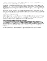
Page 6: ...o speakers to the A and B jacks on the PowerSwap using standard instrument cables Connecting MIDI to the PowerSwap Connect a standard MIDI cable between your MIDI foot controller MIDI OUT jack and the PowerSwap MIDI IN jack Connect an additional cable between the MIDI THRU jack on the PowerSwap and the MIDI IN jack of the next MIDI device in your chain as you normally would The PowerSwap does not ...

Page 7: ...ary footswitch Connecting Power to the PowerSwap Attach the supplied modular power supply to the power input on the PowerSwap If you will be using a power substitute then it should supply 9V DC at 100ma using a 2 1mm connector with center pin positive You can operate the unit safely with up to 12V DC supplies without damage Operation beyond this voltage may cause damage to the unit and void the wa...

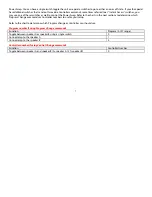
Page 8: ... in the next sections to determine which Program Change commands or Controller numbers to use for your setup Refer to the chart to determine which Program change or Controller you should use Program number if using Program Change commands Function Program 0 127 range Toggle between speaker A or speaker B using a single switch 0 Connect amp to the speaker A 1 Connect amp to the speaker B 2 Controll...

Reviews: