background image

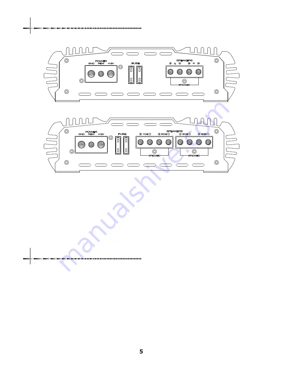
+12V ( POWER CONNECTION )

This must be connected to the positive terminal ( +12V ) of 
the battery. Recommended wire is 4 gauge 

FUSE( 40A x 2 )

Fuses protect the amplifiers from electrical damages.

SPEAKER OUTPUTS 

it connects amplifier to speakers. Minimum speaker cable is 12 gauge. 
Minimum impedance is 2ohm stereo or 4ohm mono.

GND ( GROUND CONNECTION )

It is connected to the negative or ground cables of the Vehicle. 
Recommended cable is 4 gauge.

REM ( REMOTE )

It is connected to sw12V with a trigger cable coming 
from the headunit.
 

Q2-200  OUTPUT ENDPANEL

Q4-90 & Q4-120  OUTPUT ENDPANEL

+12V ( POWER CONNECTION )

Before mounting SoundQubed amplifiers, please disconnect the negative (-) wire from battery to protect any 
accidential damage to SoundQubed amplifiers and car audio system. 
Q1-750, Q1-1200.2, Q2-200, Q4-90 & Q4-120 are designed to use 4 gauge power cable and ground connection and 
equipped with fuses. 
Q1-2200.2 and Q1-4500 are using 0 gauge power and ground connection and not equipped with fuses
Connect the power cables to power terminal labeled as +12V.
You have to install the external fuses on the power cable for Q1-2200.2 and Q1-4500 
Connect one end of fuse holders to the power cable and the other end of fuse holders to positive battery within 
20cm of the same cable.

CLASS AB MULTI-CH OUTPUT ENDPANEL

POWER, GROUND, REMOTE CONNECTION

Summary of Contents for Q1-1200.2

Page 1: ...Owner s Manual Q1 750 Q1 1200 2 Q1 2200 2 Q1 4500 Q2 200 Q4 90 Q4 120 HIGH PERFORMANCE AMPLIFIER ...

Page 2: ...n High power sound quality digital monoblock amplifiers Fully working down to 4 2 1 ohm Linked down to 2ohm 2 3oz copper printed circuit board High current mosfet switching devices 24dB Oct precision crossover Oversized 0 gauge power ground terminal The highest possible efficiency and quality with hand wound power supply transformers 4 ways of acurate protection circuits Speaker short DC offset Lo...

Page 3: ...control Remote level control adjusts the level LPF CROSSOVER FREQUENCY 35 to 250Hz 24dB Oct Controls the low pass point for the speaker outputs OUTPUT MASTER INPUT SLAVE OUTPUT MASTER INPUT SLAVE connection makes 2pcs of soundQubed amplifiers as daisy chain connection to 2 ohm Do not use output master input slave connection as 1 ohm SPEAKER OUTPUTS it connects SoundQubed amplifiers to speakers Min...

Page 4: ...z 105dB 200 8V 0 2V 20Hz 5KHz HPF FULL LP BP 50Hz 5KHz 0 18dB Included 2 pcs Double sided board 4 ga 40A x 2 pcs Q4 90 90W x 4 130W x 4 260W x 2 20Hz 30KHz 105dB 200 8V 0 2V 20Hz 5KHz HPF FULL LP BP 50Hz 5KHz 0 18dB Included 2 pcs Double sided Board 4 ga 40A x 2 pcs Q4 120 120W x 4 170W x 4 340W x 2 20Hz 30KHz 105dB 200 8V 0 2V 20Hz 5KHz HPF FULL LP BP 50Hz 5KHz 0 18dB Included 2 pcs Double sided ...

Page 5: ...ifiers input section HIGH PASS FILTER 20Hz 5KHz 12dB Oct Control the high pass frequency for the speaker output X OVER HPF FULL BP BP It selects crossover as High pass Full Low pass and band pass filter The selected crossover has effect and bass pass is capable LOW PASS FILTER 50Hz 5KHz 12dB Oct Control the low pass frequency for the speaker output BASS BOOST 0 to 18dB 45Hz It controls boost REMOT...

Page 6: ...T ENDPANEL 12V POWER CONNECTION Before mounting SoundQubed amplifiers please disconnect the negative wire from battery to protect any accidential damage to SoundQubed amplifiers and car audio system Q1 750 Q1 1200 2 Q2 200 Q4 90 Q4 120 are designed to use 4 gauge power cable and ground connection and equipped with fuses Q1 2200 2 and Q1 4500 are using 0 gauge power and ground connection and not eq...

Page 7: ...efully Before you start your installation Please take all steps into consideration or you can have SoundQubed authorized distritutors to check installation and set your car audio systems Mounting preparation Disconnect the negative battery cable before mounting SoundQubed amplifiers or making any connections Check the battery and alternator ground connections Make sure they are properly connected ...

Page 8: ...ype of the terminals on each speaker Strip 3 8 of insulation from the end of each cable and twist the cables strands together tightly Make sure there insulation from the end of each cable and twist the cables together tightly Make sure there are no stray strands that might touch other cables or terminals and cause a short circuit Crimp spade lugs over the cable ends or tin the ends with solder to ...

Page 9: ...e following connection and diagram carefully to make correct connection Digital monoblock s input connection Step 1 Connecting master amplifier to the headunit Step 2 Set master amplifier s output master and input slave switch to output master position Step 3 Connect the master and slave amplifiers s rca jack as diagram Step 4 Set slave amplifier s output master and input slave switch to input sla...

Page 10: ...tion Please make sure the subwoofer speakers impedance Linakble minimum impedance is 1ohm and connect cables as following Step 1 Connect speaker cable on master amplifier to subwoofer Step 2 Connect speaker cable on slave amplifier to subwoofer Step 3 Connect speaker cable on master amplifier to speaker cable on slave amplifier 8 2 ohms ...

Page 11: ...Q2 200 1channel mode speaker connection Q2 200 2channels mode speaker connection Q2 200 3channels mode speaker connection 8 4ohms 8 4ohms Q2 200 SPEAKER CONNECTION DIAGRAM ...

Page 12: ...Q4 90 Q4 120 2channel mode speaker connection Q4 90 Q4 120 3channels mode speaker connection 8 4ohms Q4 90 Q4 120 SPEAKER CONNECTION DIAGRAM 8 4ohms 8 4ohms ...

Page 13: ...Q4 90 Q4 120 4channel mode speaker connection Q4 90 Q4 120 5channel mode speaker connection Q4 90 Q4 120 SPEAKER CONNECTION DIAGRAM 8 4ohms ...

Page 14: ...ow and no obstruction around SoundQubed amplifiers 3 Speaker Short Pls make sure the speaker wire connection and re route speaker wires 4 DC offset When oer 4V DC SoundQubed amplifiers will be protected Pls check whether SoundQubed amplifiers work after removing RCA input If SoundQubed amplifiers work after removing RCA input then pls measure DC by checking RCA input L and R DC is over 4V at input...

Page 15: ......

Page 16: ......

Reviews: