background image

13

SL-6 POWERING AND WIRELESS SYSTEM

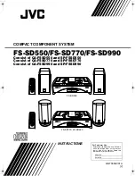
To access the Receiver Overview screen from the Main menu:

1.  Press the MENU button.

2.  Turn and press the Headphone encoder to select SL-6 > Receiver Overview.

Highlighted receiver

688 channel

Receiver number Transmitter battery level

Receiver frequency

RF signal strength

Pre-fade level

When supported by the transmitter, the transmitter battery level is indicated by 

the color of the battery icon: Green = over 50%, Yellow = over 20%, Orange = 

over 10%, Red = less than 10%. Whenever the transmitter battery level infor

-

mation is not supported by the transmitter, the icon is black.

Unislot Receivers

Configuration of unislot receivers is done on the receivers themselves, not from 

the 688; therefore, the Receiver Details screen is not available for unislot re

-

ceivers.

Using SuperSlot Receivers

When the 688 is powered on, the SL-6 will power receivers automatically, and 

attached SuperSlot receivers will boot up with their panel buttons locked.


i

Sound Devices recommends, if the 688 is powered on, you do not power down at-

tached SuperSlot receivers. If SuperSlot receivers are powered down manually (by 

unlocking the receivers’ front panel buttons), the receivers will not be recognized 

until they are powered on manually and the 688 is rebooted.

SuperSlot receivers can be configured from the 688 user interface. Detailed 

information for each attached SuperSlot receiver is displayed on the 688 via a 

Receiver Details screen. Adjustments to SuperSlot receivers may be made from 

this screen.
The screen’s title will show the type or model of the receiver. Based on your 

receiver, information on screen could vary; refer to the receiver manufacturer’s 

documentation provided with your receiver(s) for more information.

Summary of Contents for SL-6

Page 1: ... SL 6 Powering and Wireless System for the 688 User Guide interstage Phistersvej 31 2900 Hellerup Danmark Telefon 3946 0000 fax 3946 0040 www interstage dk pro audio with a smile ...

Page 2: ... Microsoft Corporation in the U S and other countries All other trademarks herein are the property of their respective owners FCC Notice This device complies with part 15 of the FCC Rules Operation is subject to the following two conditions 1 This device may not cause harmful interference and 2 This device must accept any interference received including interference that may cause undesired operat...

Page 3: ...3 Revision History This table provides the revision history of this guide Rev Date Description 1 A June 2015 Initial Official Publication ...

Page 4: ...SL 6 User s Guide 4 ...

Page 5: ...uts 8 SL 6 Power Settings 8 Using Antenna Distribution 9 Using Wireless Receivers 10 Selecting a Wireless Source 11 Accessing the Receiver Overview Screen 11 Unislot Receivers 12 Using SuperSlot Receivers 12 Receiver Details Screen Example A 13 Receiver Details Screen Example B 14 SL 6 Specifications Powering 16 Antenna Distribution 17 Physical 17 ...

Page 6: ...Slot 2 Receiver Slot 3 Receiver Slot 1 Antenna Connector A Antenna Distribution lead B Feature Description Receiver Slots Each slot accepts one single or dual channel SuperSlot or unislot receiver The connection provides power to the receiver and connects the receiver s audio output directly to the 688 Antenna Distribution leads SMA connectors with right angle adapters are used to connect receiv e...

Page 7: ... draw from the active SL 6 power source Hirose 4 pin or NP 1 Each output is on by default but can be switched off from the POWER section of the Main menu USB Charging Port Standard USB 5 V DC output that draws from the active SL 6 power source Hirose 4 pin or NP 1 L L The USB port on the SL 6 is designed for charging only not for data transfer Left Panel The left panel of the SL 6 provides the NP ...

Page 8: ...attached will continue to operate using those power sources L L Power sources connected directly to the 688 external DC or the internal AA bat teries will not power the SL 6 or any attached peripheral devices When activated the SL 6 including wire less receivers and any equipment con nected to the SL 6 DC outputs will be shut down When activated the 688 and CL 6 if attached will be shut down When ...

Page 9: ...e DC outputs will be turned off in descending order output 4 1 until power draw drops below 45 watts First the USB charging port will be disabled then DC Output 4 DC Output 3 DC Output 2 and finally DC Output 1 You can manually turn outputs back on when power draw drops below 45 watts SL 6 Power Settings When the SL 6 is attached the following settings are available in the Main menu s POWER sectio...

Page 10: ...lder mounted antennas are one example Care should be used with antenna selection in this scenario Some antennas such as quarter wave also known as quarter wave whip antennas require a ground plane metallic reflective surface usually perpendicular to the antenna Others such as a half wave antenna and log periodic antenna Also referred to as paddle antenna can be remotely mounted and do not require ...

Page 11: ... SL 6 L L Mounting procedures for receiver models may vary Refer to the receiver manufac turer s documentation for your receiver and follow the specific mounting instruc tions The Lectrosonics SRb5P can not be connected to slot 1 of the SL 6 Using the blue spacer Provided with the receiver the SRb5P can be connected to slot 2 or 3 1 Power off the 688 2 The SL 6 ships with rubber slot protectors th...

Page 12: ...e active assign ments 4 Do any of the following X X Turn the Select encoder to move the orange highlight vertically and press the encoder to activate or deactivate the route X X Turn the Headphone encoder to move the orange highlight horizontally and press the encoder to activate or deactivate the route L L When a wireless receiver output is routed to a 688 input that channel s input source is set...

Page 13: ...for unislot re ceivers Using SuperSlot Receivers When the 688 is powered on the SL 6 will power receivers automatically and attached SuperSlot receivers will boot up with their panel buttons locked L L Sound Devices recommends if the 688 is powered on you do not power down at tached SuperSlot receivers If SuperSlot receivers are powered down manually by unlocking the receivers front panel buttons ...

Page 14: ...e edit ing mode 3 Turn the Headphone encoder to adjust the value 4 Press the Headphone encoder to accept the value Receiver Details Screen Example A Information provided on the Receiver Details screen depends on your receiver model This guide provides a couple of examples The following example of the Receiver Details screen is for a Lectrosonics SRb Refer to Lectrosonics docu mentation for further...

Page 15: ...input to which it is routed Frequency Displays the frequency to which the receiver is currently tuned Whole number and decimal number are adjusted independently Decimal adjustments in 1 Normal tuning or 025 increments Fine tuning To adjust frequency X X Turn and press Headphone encoder Block Tx Switch Displays the block number and transmitter switch value Tuning Displays current tuning group When ...

Page 16: ...n is black L L This information is only provided when supported and supplied by the transmitter GR Displays the current group number of the receiver To set the group number X X Turn and press Headphone encoder Pre fade level Displays pre fade audio level of the receiver s output on the 688 input to which it is routed Frequency lock Lock icon is visible for channels in which the frequency is locked...

Page 17: ...ysical SL 6 Specifications Powering Name Description External Power Supply 10 to 18 V on locking 4 pin Hirose connector Pin 4 Pin 1 Mates with gold Hirose HR10A 7P 4P DigiKey HR110 ND or silver Hirose HR10 7P 4P DigiKey HR100 ND locking connec tor PowerSafe 10 second power reserve to SL 6 688 and CL 6 if connected and attached peripherals USB Charging port 5 V 2 A max DC Outputs 1 2 Locking coaxia...

Page 18: ...mpedance 50 ohm Antenna bias voltage 12 V 200 mA Antenna filter ranges 470 870 MHz 470 700 MHz 470 590 MHz 580 700 MHz Physical Name Description Dimensions H x W x D 1 4 in x 12 7 in x 5 6 in 3 6 cm x 32 3 cm x 14 2 cm Weight without receivers 2 lbs 6 oz 1 08 kg ...

Page 19: ...19 SL 6 SPECIFICATIONS ...

Page 20: ...re information about products and accessories visit us on the web at www sounddevices com Customer Support Toll Free 800 505 0625 support sounddevices com http www sounddevices com support http forum sounddevices com interstage Phistersvej 31 2900 Hellerup Danmark Telefon 3946 0000 fax 3946 0040 www interstage dk pro audio with a smile ...

Reviews: