Sound Devices CL-12 User Manual Download Page 13

13

CL-12 LINEAR FADER CONTROLLER

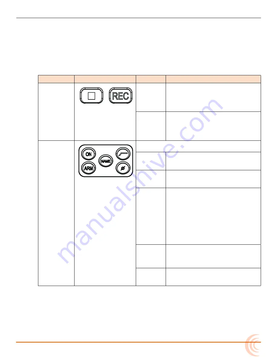
Right: Buttons and HP Encoder

The area that spans the right side of the mixing surface has transport controls 

and numerous buttons for quick access to many key features. For convenience, 

the buttons are grouped in sections according to common functionality.


i

Not all features described here are available with every mixer. For more 

information, see 

CL-12 Comparison Chart

.

s

ection

B

uttons

n

ame

D

escription

Transport 

Controls

Record

While the Transport Control on the 

mixer operates normally when the CL-

12 is attached, this alternate, backlit 

Record button provides an additional 

control for starting a recording.

Stop

This alternate, backlit Stop button 

provides an additional control for stop

-

ping a recording or playback, or (when 

stopped) viewing the next take’s file 

name.

Channel 


Select Tools


i

Channel Select tools operate on the currently 

selected channel(s).

ON

Press to toggle a channel on or 

off. When on, the input’s ON LED 

illuminates yellow.

ARM

Press to arm or disarm the channel. 

When armed, the input’s ARM LED 

illuminates red.

NAME

Press this button to display and edit 

the currently selected channel’s track 

name. This name is embedded as 

metadata within the recorded files.


i

This functionality only works when 

one input is selected. If multiple 

inputs are selected when the NAME 

button is pressed, a warning message 

appears instructing the user to select 

a single input.

HPF 

Press to toggle on or off high-pass 

filtering for a selected input channel. 

For more information, see 

Using High-

pass Filters

.

Phase

Press to toggle the phase of aselected 

input channels. When inverted, the 

PHASE button illuminates orange.

Summary of Contents for CL-12

Page 1: ... CL 12 Linear Fader Controller for the 6 Series User Guide ...

Page 2: ...Microsoft Corporation in the U S and other countries All other trademarks herein are the property of their respective owners FCC Notice This device complies with part 15 of the FCC Rules Operation is subject to the following two conditions 1 This device may not cause harmful interference and 2 This device must accept any interference received including interference that may cause undesired operati...

Page 3: ...the 6 Series of Mixers Recorders New Feature Comparison Chart on page 15 Updated CL 12 Sub menu on page 16 New section Adjusting Trim Levels 664 only on page 19 New section Adjusting Trim Levels 633 only on page 19 Updated Adjusting Output or Track Levels on page 20 Updated Using High pass Filters on page 26 Updated table in Configuring User Programmable Buttons on page 27 2 B Feb 2016 v2 11 Minor...

Page 4: ...User Guide 4 ...

Page 5: ...ls 688 only 19 Adjusting Trim Levels 664 only 19 Adjusting Trim Levels 633 only 19 Routing Input Channels 20 Adjusting Output or Track Levels 20 Configuring Output Meters 688 only 21 Arming L R X1 X2 Tracks 21 Using the 3 Band Equalizer 688 only 21 Accessing the EQ Submenu 23 Bypassing EQ 24 Setting the Q Factor 24 Setting LF and HF Frequency Defaults 25 Setting LF and HF Filter Types 25 Setting E...

Page 6: ...User Guide 6 ...

Page 7: ...in the CL 12 Quick Start Guide The front and back panels of the CL 12 provide a number of connection ports for a variety of purposes The front panel has two headphone outputs a inch and a 3 5 mm TRS jack 1 4 inch 3 5 mm The back panel provides the connections required for attaching the CL 12 to 6 Series mixers plus ports for other peripherals Back Panel Overview of Panels Altered Functionality Sel...

Page 8: ...a robustness between the mixer and the CL 12 in the event of static shock DC Boost Input Connect a micro USB power cord not included with the CL 12 to this port 5V on the CL 12 is required for connecting a CL 12 to either a 664 or 633 When using a CL 12 with a 688 this port is optional but recommended for providing additional DC power when necessary such as for powering a high current draw USB key...

Page 9: ...12 s top panel the mixing surface is divided into three areas Top comprised of the EQ and OUTPUTS sections Left comprised of the Channel Strip section Right comprised of the Headphone encoder and several sections of but tons for various functions such as transport control channel selection etc ...

Page 10: ...l as LED metering and the Power LED EQ Section OUTPUTS Section L L Not all features described here are available with every mixer For more information see CL 12 Comparison Chart Feature Description EQ Controls There are four rotary encoders in the EQ section These 3 band EQ controls include LF gain MID frequency gain and HF gain Other EQ parameters such as Q factor and filter type are set up from ...

Page 11: ...ng L R X1 X2 Tracks Left Channel Strip Section The area that spans the majority of the mixing surface comprises 12 channel strips Each strip is comprised of 12 linear faders SEL and PFL buttons LED indicators and LED meters The CL 12 s low latency faders allow for responsive level adjustment L L Not all features described here are available with every mixer For more information see CL 12 Compariso...

Page 12: ...ator Illuminates yellow to indicate the input channel is on ARM Indicator Illuminates red to indicate the corresponding isolated track ISO is armed for recording MIXASSIST Indicator Illuminates to indicate MixAssist auto mixing activity When the input is open the LED is green As the input closes the LED is turned off PFL Buttons Pre Post Fade Listen Activates or deactivates pre or post fade listen...

Page 13: ...ping a recording or playback or when stopped viewing the next take s file name Channel Select Tools L L Channel Select tools operate on the currently selected channel s ON Press to toggle a channel on or off When on the input s ON LED illuminates yellow ARM Press to arm or disarm the channel When armed the input s ARM LED illuminates red NAME Press this button to display and edit the currently sel...

Page 14: ...next take s Notes Press NOTES again to save and exit L L Hold NOTES button down for 1 second to view Phrase List screen INC Increments the scene name according to settings configured via File Storage Scene Increment Mode FALSE Moves last take to the False Takes folder and decrements the take number by 1 Toggles the circle status of the current take which prepends the at symbol to file name and upd...

Page 15: ... disabled N A Feature Comparison Chart Feature availability is contingent on the model of the mixer to which the CL 12 is connected The following table outlines the differences between the various 6 Series models CL 12 Feature 688 664 633 Number of linear faders 12 12 6 DC Boost micro USB power connection Optional Required Required 3 band semi parametric equalizer MixAssist Metering and Control Su...

Page 16: ... only allow for control of track levels this menu option is not available when a CL 12 is connected to them For more information see Adjusting Output or Track Levels L X2 Metering Configure LED meters to display either output or track levels Since the 664 and 633 only allow for metering of track levels this menu option is not available when a CL 12 is connected to them For more information see Con...

Page 17: ...button is selected are ON ARM NAME HPF PHASE EQ and Routing to L R X1 X2 L L NAME and EQ can only be adjusted for a single channel To select an input channel X X Press the input s SEL button L L Press the input s SEL button again to deselect it or press any other SEL button to change selection To select multiple input channels do either of the following X X Simultaneously press multiple SEL button...

Page 18: ...tapped again or another is selected When active the PFL button illuminates and the Input Settings screen for the active PFL input is displayed on the mixer s LCD Setting SEL to follow PFL The CL 12 provides the SEL follows PFL option for automatic selection of an input channel when its PFL button is pressed Think of SEL follows PFL as a fast one touch method for gaining access to PFL the Input Set...

Page 19: ...er may be used to adjust trim for inputs 7 12 via the Input Settings screen To adjust the trim level for inputs 7 12 1 Slide the input s PFL switch on the CL 6 to the right to access the Input Set tings screen on the mixer s LCD 2 Turn the SELECT encoder to adjust trim for the input The trim gain is dis played on the mixer s LCD Adjusting Trim Levels 633 only Pan Mini Fader 4 6 becomes Trim when C...

Page 20: ...ous pan control set an input channel s routing to both L and R then use the Pan control on the 6 Series mixer to smoothly adjust pan This will ensure that an input s pan position will be retained when disconnecting and recon necting the CL 12 Adjusting Output or Track Levels The CL 12 has four rotary controls labeled OUTPUTS that are used for adjusting either output or track levels based on which ...

Page 21: ...M button 2 Press the rotary OUTPUT control s corresponding to the output track s you want to arm When armed each output track s ARM LED illuminates red Using the 3 Band Equalizer 688 only The CL 12 adds 3 band EQ to the 688 EQ is only available when sample rate is 48 048 kHz or less and it is only available for adjustment when CL 12 is connected LF is a fixed 100 Hz EQ by default with 12 dB gain a...

Page 22: ...es green When EQ is applied to a selected input the EQ screen also appears for the selected input on the mixer s LCD For instance in the following example EQ is applied to channel 1 CH 1 LF is set at 10 dB and HF is set to 10 dB while MID frequency and gain are bypassed In the example high pass filtering is off the Q factor is set to 1 0 and both LF and HF filtering is set to Peaking It is not pos...

Page 23: ... 300 Hz Default is 100 Hz This may be adjusted individually for each channel HF Freq Values range from 8 kHz to 16 kHz Default is 10 kHz This may be adjusted individually for each channel For more information see Setting LF and HF Frequency Defaults LF Filter Type Set to either Peaking or Shelving This may be adjusted individually for each channel HF Filter Type Set to either Peaking or Shelving T...

Page 24: ...eapply the last non zero gain value for LF MID or HF respectively When an EQ band is bypassed its EQ LED goes out Setting the Q Factor The Q factor controls the bandwidth that will be cut or boosted by the equalizer To set the Q factor 1 Press MENU 2 Select CL 12 EQ Q Factor 3 Select one of the following options 0 707 1 0 1 414 or 2 0 The lower the setting the wider the bandwidth which means more ...

Page 25: ...g LF and HF Filter Types The CL 12 s EQ offers two types of filters Peaking and Shelving and these may be adjusted individually for each input Filter Sample Image Description Peaking A peaking filter will create a hill or peak like boost or cut around a particular frequency The spread of the peak will vary based on the Q factor Shelving A shelving filter will slope up or down to a particular point...

Page 26: ...nel The HPF button illuminates when high pass filtering is on 3 633 688 only Adjust the HPF value via the Input Settings screen When high pass filtering is on the HPF value is fixed at 150 Hz on the 664 but may be changed via in the Input Settings screen on the 633 or 688 Also on the 688 the EQ screen appears on the mixer s LCD The Head phone encoder may be used as an alternative way to adjust the...

Page 27: ...rent 6 Series mixers Option Description 688 664 633 Take List Displays the Take List screen File List Displays the File List screen Play Toggles between play and pause FFWD Fast forward or skip to next file REW Rewind or skip to previous file Slate Toggles slate on and off Tone Toggles tone on and off FAV Duplicates the action of the FAV switch Select Duplicates the action of pressing the Select e...

Page 28: ...ironment the brightness of the CL 12 s LED may require adjustment To adjust LED brightness 1 Press MENU 2 Select LED Brightness 3 Turn the Headphone encoder to adjust value up or down in 1 increments from a minimum of 5 up to 100 L L TIP LED brightness may be further boosted by connecting a USB 5 V source to the DC Boost Input port on the back panel of the CL 12 Specifications The following specif...

Page 29: ...1 608 524 0625 Fax 1 608 524 0655 Product Information For more information about products and accessories visit us on the web at www sounddevices com Customer Support Toll Free 800 505 0625 support sounddevices com http www sounddevices com support http forum sounddevices com ...

Reviews: