


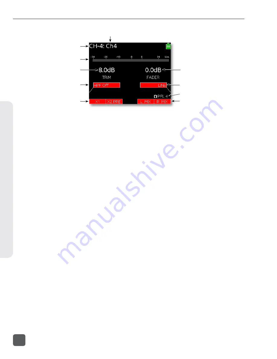
3) Input Meter
12) Trim Gain
2) Input Number
1) Track Name
5) HPF Frequency
6) Aux Bus Assignment
8) Input Selection
9) Headphone Source / Level
10) LR Bus Assignment
4) Current Fader Gain
1)
Track Name
The name of the input’s ISO track. The
Track Name can be edited directly from
the Input Settings Screen. (
2)
Input Number
The Input’s number (1 through 6).
3)
Input Meter
Displays the Input’s signal level and
limiting activity. The level displayed is
the level to the Iso Track and will be pre-
or post-fader depending on the Iso Track
Status. Meter ballistics can be set globally
from VU or Peak+VU in Setup Menu item
SYSTEM > Meter Ballistics
. (
4)
Current Fader Gain
The dB value of the input’s fader. (
“Trim and Fader Relationship”, page 15
5)
HPF Frequency
Displays the frequency of the Input’s high
pass filter (Or
HPF Off
when the high
pass filter is off). To adjust the high pass
filter, press the Select Encoder, then turn
the Select Encoder. (
6)
Aux Bus Assignment
Displays the status of the Input’s assign-
ment to the X1 and X2 Output Buses.
Inputs can be routed to X1 and X2 pre- or
post-fader. Slide the Mic / Tone Switch
left for the X1 bus and right for the X2
bus to cycle through the available op-
tions. Routed signal is indicated by a red
background and unrouted signal by a
black background. (
7)
Limiter Activity
Indicates that limiting is occurring on the
Input. (
8)
Input Source
Displays the selected input type. To
change the input type, press the Head-
phone Encoder, turn it to make a selec-
tion, then press it again to confirm the
selection. (
9)
Headphone Source / Level
Currently active Headphone Source.
Displays monitor gain during adjustment.
See “Headphone Monitoring”, page 22
10)
L,R Bus Assignment
Displays the status of the Input’s assign-
ment to the main Left and Right buses.
Slide the RTN / FAV Switch to the right
to toggle routing of Inputs 1, 2, and 3.
Slide the RTN / FAV Switch to the left or
right to toggle routing of Inputs 4, 5, and
6 to the Left or Right bus. Routed signal
is indicated by a red background and un-
routed signal by a black background. (
11)
Input Polarity
Slide the RTN / FAV Switch left to toggle
input polarity. Available on Input 2 only.
12)
Input Trim
Displays the trim gain on inputs 4, 5, and
6 as well as any input with the source set
to AES42 or AES3. Trim is adjusted on
these Inputs by rotating the Select En-
coder while viewing the Input Settings
Screen. (
See “Trim and Fader Relationship”,
633 User Guide and Technical Information
12
v. 1.02
Features and specifications are subject to change. Visit www.sounddevices.com for the latest documentation.
Scr
een Ov
er
vie
w