


Page 22 / 22
Assembly instructions
Compact-Line kit
www.sorotec.de
V 2.1.0
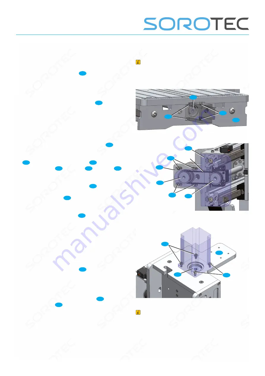
Assembly of the axis drives
X axis
• Push the claw coupling
13
as far as possible
onto the shoulder of the ball screw and fix it with
the locking screw.
• Insert the stepper motor into the claw coupling
and screw it to the rear end plate
28
.
• Fix the stepper motor with the safety screw of
the claw coupling.
Y axis
• Temporarily remove end plate Y left
2
.
•
Screw the stepper motor to the motor flange Y
19
(either with M5x25 screws
C5
OR with
M4x16 screws
B2
, washers
V
and nuts
K
);
Slightly counter-tighten the screws.
• Push the toothed belt wheel
35
onto the
output shaft of the stepper motor, align it with the
toothed belt wheel
36
on the ball screw and fix it
with the locking screw.
• Put on the toothed belt
34
and tension it by
moving the stepper motor; Tighten the stepper
motor mounting screws.
• Screw the end plate Y left back to the portal
beam.
Z axis
• Push the claw coupling
13
as far as possible
onto the shoulder of the ball screw and fix it with
the locking screw.
• Insert the stepper motor into the claw coupling
and screw it to the motor flange Z
20
using
M4x16 screws
B2
.
• Fix the stepper motor with the safety screw of
the claw coupling.
Note
The stepper motors shown below are not part of
the scope of delivery. The illustration is intended
to clarify the structure of the axis drives.
Fig. 30: Assembly stepper motor X axis
Fig. 31: Assembly stepper motor Y axis
Fig. 32: Assembly stepper motor Z axis
Note
Claw couplings can cause loud noises during
operation. In this case, lubricate the plastic buffer
with a little Vaseline. Never use normal grease
or lubricating oil! Ordinary lubricants attack the
plastic and can destroy it.
13
B2
B2
28
35
2
C5
19
C5
36
20
B2
13
B2