background image

13

XGS 5500/6500

Operating Instructions

Redundant Power Supply

The XGS 5500/6500 models are equipped with a 1+1 redundant power supply. The power 
supply system consists of two separate power supply units. This power supply system 
increases the availability of the security appliance, since a defective power supply unit can 
be exchanged easily and quickly during operation.

When the system is running error-free, the PS1 and PS2 LEDs on the front panel will show 
green. The LED on the rear of the power supply module will also show green. In the event 
of a defect in a power supply (including loss of AC power or out-of-specification AC power) 
the appropriate front panel LED will show red, and the LED on the rear of the power supply 
module will show orange.

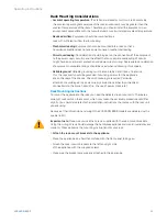
Important note:

 If you need to change a power unit because of a defect, remember to 

remove the defective power unit from the power supply system, otherwise the whole 
security appliance will fail.

Protect yourself from potential burns by wearing protective gloves when exchanging a 
power supply unit.

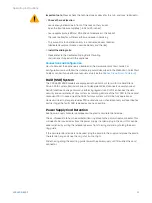
Only use power units which you purchased directly from Sophos or from a Sophos 
distribution partner. Please remember that any warranty claims are voided for the security 
appliance if a defect has been caused by the use of power units which are not suited for the 
system.

Exchanging a power supply unit

1. 

Remove the cord, taking care to release the cord from the cord retention device. 

2. 

Move the green lever of the power supply to be replaced toward the center of the 
chassis and, using the handle by the power supply fan, pull out the supply.

3. 

Plug in the replacement supply, making sure it is fully seated and that the 
green handle is moved toward the edge of the channel. If the green handle 
is not sufficiently moved, it will prevent the cord from being plugged in.

4. 

Plug the power cable back into the connector of the new power supply unit and 
check the following LED displays:LED of the new power supply unit lights green. 

5. 

Fix the cord retention

SFP/ SFP+/QSFP+ ports

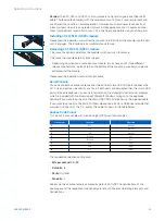
The XGS 5500/6500 models offer a variety of SFP/SFP+/QSFP ports allowing you to 
plugin various GBICs (transceivers) to connect to high-speed fiber or copper networks. The 
abbreviation SFP GBIC stands for small form-factore plugable GigaBit interface converter, a 
flexible interface which changes electronic signals into optical signals. The converters used 
with the appliance are often also called Mini-GBIC or New GBIC.

To use SFP/SFP+/QSFP+ ports, you will need the appropriate transceivers or DAC cables 
(combining cables and transceivers into one). These are not delivered with the appliance 
but available through your Sophos partner. There are different transceiver types, and the 
required type is determined by the existing network.

Summary of Contents for XGS 5500

Page 1: ...Operating Instructions XGS 5500 6500...

Page 2: ...ls The following symbol and its meaning appears in the Hardware Quick Start Guide Safety Instructions and in these Operating Instructions Caution and Important Note If these notes are not correctly ob...

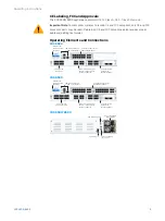
Page 3: ...l module COM Micro USB RJ45 2 x USB 3 0 MGMT port 2 x expansion bay shown with optional modules F1 F4 F5 F8 fiber ports LAN 1 8 8 x GbE copper fixed Incl 2 bypass pairs ports 1 2 and 3 4 Multi functio...

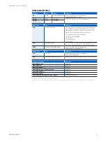
Page 4: ...nnect a USB 2 0 or 3 0 compatible device to this port e g USB thumb drive UPS 3G 4G dongles MGMT RJ45 10 100 1000 Mbps We recommend using this dedicated port to connect your Admin PC Module Slots Type...

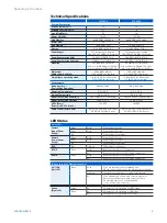
Page 5: ...C to 70 C 20 C to 70 C Operational Storage Humidity 10 to 90 non condensing 10 to 90 non condensing Operational Storage Altitude 2000 5791 m 2000 5791 m MTBF hours Telcordia SR 332 Issue 3 135099 135...

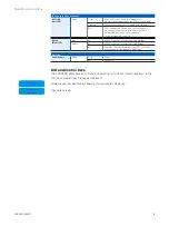
Page 6: ...do not function correctly Speed Right LED Blue On If SFP connector is operating at 10 000 Mbps Amber On If SFP connector is operating at 1 000 Mbps Off Either the LED is not working or the SFP connec...

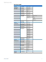
Page 7: ...0 Main Menu 2 Network Menu Network Menu 1 Show Port A1 LAN Port A1 LAN 172 16 16 16 Network Menu 2 Show Port A2 WAN Port A2 WAN IP NOT ASSIGN Network Menu 3 Show Port A3 NA Port A3 NA IP NOT ASSIGN N...

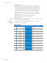
Page 8: ...ill shut down the system completely and reboot Control Key Functions The current menu is left When the key is pressed a couple of times the modifications are discarded and the initial state will be di...

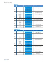
Page 9: ...key to continue 8 Factory Reset 1 Confirm Asks for Confirmation 9 ENTER Shutdown Complete Reboot Machine S NO Action Item press What you see on the LCD What it means 1 SOPHOS Protection Appliance is...

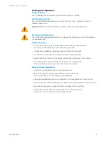
Page 10: ...tabilizers should be attached to the rack In multiple rack installations the racks should be coupled together Always make sure the rack is stable before extending a component from the rack You should...

Page 11: ...mes To ensure this the rack itself should be grounded Grounding screws for the appliance are on the rear of the chassis Chassis Grounding is required Particular attention should be given to power supp...

Page 12: ...ith a RAID 1 system with two Solid State Drive A RAID system redundant array of independent disks connects several physical Solid State Drive to one particularly performing logical drive RAID 1 enhanc...

Page 13: ...power units which are not suited for the system Exchanging a power supply unit 1 Remove the cord taking care to release the cord from the cord retention device 2 Move the green lever of the power supp...

Page 14: ...he module Please read the operation manual to the module Serial Console You can connect a serial console to either the RJ45 or micro USB COM port to access the CLI Only one port can be used at any tim...

Page 15: ...9409 9100 Email sales sophos com au Asia Sales Tel 65 62244168 Email salesasia sophos com Copyright 2021 Sophos Ltd All rights reserved Registered in England and Wales No 2096520 The Pentagon Abingdon...

Reviews: