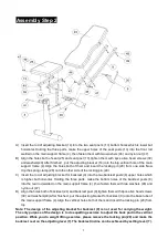
Soozier A91-086 Manual Download Page 6


Assembly Step 2 


A)  Insert the rod of adjusting bracket (14) into the two seat post’s (13) bottom holes which is lower but 

horizontal.  Holding  the  three  parts,  make  the  upper  holes  of  the  seat  posts  (13)  into  the  front  rod 

welded on the main support frame (4) ,then fasten them with two washers (46) and nylon nut (47). 

B)  Align the holes both of seat (25) and seat post (13),tighten them with 4pcs allen head screws (39) 

and washers(49).After finished , put the adjusting bracket (14) into the big vertical hole of the main 

support frame (4).Align the holes both of them and insert the locking pin (20) from one side .Now 

clip the spring clamp (28) onto the other side of the locking pin.(20) 

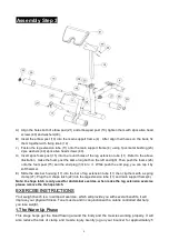
C)  Insert the rod of adjusting bracket for backrest (9) into the two backrest posts’(8) upper holes which 

is  higher  but  horizontal.  Holding  the  three  parts,  make  the  bottom  holes  of  the  backrest  posts  (8) 

into the rear rod welded on the main support frame (4) ,then fasten them with two washers (46) and 

nylon nut (47). 

D)  Align the holes both of backrest (24) and backrest post (8),tighten them with 4pcs allen head screws 

(39) and washers(49).After finished , put the adjusting bracket for backrest (9) onto the base tube of 

the main support frame (4).Align the vertical holes both of them and insert the locking pin (20) from 

top . 

Note:  The  design  of  the  adjusting  bracket  for  backrest  (9)  is  not  used  for  carrying  the  weight. 

The only purpose of the design is to do squatting exercise to adjust the back pad in the vertical 

position. While you do weight lifting exercise, please remove the locking pin (20) and make the 

backrest  rest


on the adjusting lever (7).The backrest incline can be achieved by setting lever (7). 

Summary of Contents for A91-086

Page 1: ...GHLY READ AND UNDERSTAND INSTRUCTION IN THIS MANUAL BEFORE ASSEMBLING AND USING THIS TRAMPOLINE WARNING YOU MUST THOROUGHLY READ AND UNDERSTAND INSTRUCTION IN THIS MANUAL BEFORE ASSEMBLING AND USING T...

Page 2: ...do experience any of these conditions you should consult your doctor before continuing with your exercise program 4 Keep children and pets away from the equipment The equipment is designed for adult u...

Page 3: ...2 Exploded View...

Page 4: ...housing 76 45 1 11 Leg extension tube 1 37 Plastic housing 76 60 2 12 Stand for connection beam 1 38 Round cap 1 13 Seat post 1 39 Allen head screw M8 35 8 14 Adjusting bracket 1 40 Allen head screw M...

Page 5: ...h allen head screw 18 and curved washer 50 securely E Put the main support frame 4 stand 12 onto the connection beam 3 Make their holes in line then insert the carriage bolt 41 Finally fasten the carr...

Page 6: ...e two backrest posts 8 upper holes which is higher but horizontal Holding the three parts make the bottom holes of the backrest posts 8 into the rear rod welded on the main support frame 4 then fasten...

Page 7: ...ile push the end plug you can tap it by soft hammer E Slide the disc bar housing 17 into the bar of leg extension tube 11 then clip them with a spring clamp 27 Plug the U shape latch 22 into the leg e...

Page 8: ...and muscles wind down This is a repeat of the warm up exercise e g reduce your tempo continue for approximately 5 minutes The stretching exercises should now be repeated again remembering not to forc...

Page 9: ...1 BANC DE MUSCULATION A91 086 FR C000000 AVERTISSEMENT VOUS DEVEZ BIEN LIRE ET COMPRENDRE L INSTRUCTION DANS CE MANUEL AVANT D ASSEMBLER ET D UTILISER CE BANC DE MUSCULATION...

Page 10: ...rencontrez l une de ces conditions vous devriez consulter votre m decin avant de poursuivre votre programme d exercice 4 loignez les enfants et les animaux de compagnie de l quipement L quipement est...

Page 11: ...3 Vue clat e...

Page 12: ...1 Tube d extension de jambe 1 37 Bo tier en plastique 76 60 2 12 Support pour poutre de connexion 1 38 Casquette ronde 1 13 Tige de selle 1 39 Vis t te Allen M8 35 8 14 Support de r glage 1 40 Vis t t...

Page 13: ...t res doivent tre de la m me hauteur D Attachez le stabilisateur avant 5 au cadre de support principal 4 avec la vis t te Allen 18 et la rondelle courb e 50 solidement E Placez le cadre de support pri...

Page 14: ...e dossier 8 qui est plus haut mais horizontal En tenant les trois parties percez les trous inf rieurs des poteaux de dossier 8 dans la tige arri re soud e sur le cadre de support principal 4 puis fixe...

Page 15: ...avec un marteau doux E Faites glisser le bo tier de poteau de disque 17 dans le tube d extension de jambe 11 puis coupez les avec une pince ressort 27 Branchez le loquet en forme de U 22 dans le tube...

Page 16: ...votre syst me cardio vasculaire et les muscles se d tendre Il s agit d une r p tition de l exercice d chauffement par exemple r duire votre tempo continuer pendant environ 5 minutes Les exercices d t...

Reviews: