30
30
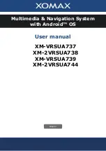
XVM-R70
6-10. SCHEMATIC DIAGRAM — LCD SECTION (3/3) — • Refer to page 23 for Waveforms and Common Note on Schematic Diagram and page 32 for IC Block Diagrams.
C604
C602
C603
R659
TP608
TP607
TP606
TP605
TP604
TP603
TP602
R627
R626
R625
R624
R623
R622
R621
R619
R618
R617
R616
R615
TP601
C601
R655
R654
R600
R602
R606
R608
R609
R610
R660
R613
R661
R614
C600
TP615
R658
R656
R657
TP600
C607
R629
R630
R631
R632
C608
R633
C611
FL601
C612
TP609
TP610
TP611
C609
C546
R528
R529
R526
R527
IC501
IC601
C620
R647
R646
C621
R645
R644
R643
R641
R642
C619
R639
R640
C626
C616
L602
C615
C614
R637
R662
C618
C617
L603
D601
C613
RV600
D600
R635
C628
D603
C622
R648
C627
C819
C820
C822
C823
C825
L803
L804
L805
L806
C828
C829
C826
C827
C824
C821
D802
D803
R831
R832
RV802
L800
C805
C838
R833
Q801
R809
R808
R805
R806
R807
C803
R804
R802
C800
R800
RV800
C802
R801
R803
C801
C810
R815
R812
R814
C809
R813
R811
R810
C806
C807
L801
TP804
TP805
TP806
TP807
L808
L810
L809
L807
D804
D805
C833
C835
C831
C832
C836
C834
C830
R819
R820
R823
R824
R825
R822
R821
R818
C813
C816
Q802
Q803
R817
C811
C814
C812
C815
JC801
R816
R827
R826
L802
TP812
TP811
TP810
TP809
TP817
TP816
TP818
TP815
TP814
TP813
L600
C606
C605
D602
C817
LCD1
R634
R604
Q601
TP612
Q600
R636
Q506
CN800
TP614
TP800
TP802
TP808
C818
TP803
C808
T800
D604
F800
IC800
Q800
IC801
Q804
RV801
D800
RV601
R638
C837
D801
C804
Note:
The components identi-
fied by mark
0
or dotted
line with mark
0
are criti-
cal for safety.
Replace only with part
number specified.
Note:
Les composants identifiés par
une marque
0
sont critiques
pour la sécurité.
Ne les remplacer que par une
piéce por tant le numéro
spécifié.
(Page 28)
(Page 29)