background image

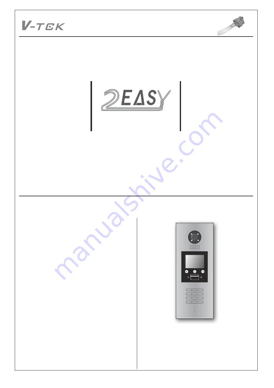
2-wire Intercom System

2 EASY

1

2

3

6

5

4

7

8

9

#

0

*

RF CARD

CONTENTS

INTRODUCTION...........................................................................2

   Installation Guide........................................................................2

CONFIGURATIONS......................................................................4

   Debug State...............................................................................4

   Work Mode.................................................................................8

   Software Update........................................................................10

   Tone Update..............................................................................10

   UI Update...................................................................................11

   Namelist Update.........................................................................12

      by SD Card..............................................................................12

      by DT-Config............................................................................13

DMR18S TECHNICAL MANUAL

Summary of Contents for 2Easy DMR18s

Page 1: ...2 3 6 5 4 7 8 9 0 RF CARD CONTENTS INTRODUCTION 2 Installation Guide 2 CONFIGURATIONS 4 Debug State 4 Work Mode 8 Software Update 10 Tone Update 10 UI Update 11 Namelist Update 12 by SD Card 12 by DT Config 13 DMR18S TECHNICAL MANUAL ...

Page 2: ... connection EB Exit button connection port EB Exit button connection port JP LK For electronic lock safety type setting refer to door station lock connections T R USB RS485 communication terminal negative T R USB RS485 communication terminal positive Bus L1 L2 non polarity bus line Surface mounting Flush mounting 1 2 4 5 6 Drill holes in the wall to match the size of screws and attach the rainy co...

Page 3: ... jumper must be taken off before connecting 3 Setup the Unlock Mode Parameter for different lock types Power on to unlock type Unlock Mode 0 by default Power off to unlock type Unlock Mode 1 4 If different unlocking time is needed to be configured change the unlock time on door station detail information refer to DT system tech nical guide JP_LK 12V 300mA Exit button Jumper position in 2 3 12V LK ...

Page 4: ...enter Doorplate Mode setting page 0 Input room number to call monitor 1 Input room number to call monitor 4 Monitor Timing Select item 4 to enter Monitor Timing setting page the setting range is from 006 600s Descriptions Input 9008 then input the Admin Code 66666666 by default Debug state menu is launched 9 0 0 8 Please Input Password 1 2 3 6 5 4 7 8 9 0 RF CARD D e b u g S t a t e 0 Redial 1 Too...

Page 5: ...ord 9 Default During working at debug state press 1 to enter tools page Press NO 2 to enter Setup item Setup page overview 1 Language Select item 1 to enter Language setting page Select the language you need Refer to the following UI Update section 2 Tone Select Select item 2 to enter Tone Select setting page Select the Tone you want Refer to the following Tone Update section Descriptions SETUP Pr...

Page 6: ...to enter About page The information includes Hardware version Software Version etc 9 Default Select item 9 to enter Default setting page Input setup code to restore factory settings 1 Add Card Select item 1 to enter Add Card setting page Cancel Save 7 Setup Code Cancel Save Hardware Version DMR18S CT a1 1 Software Version V000101 Manufacture Date Dailing Count 0006 Calling Count 0002 Unlock Count ...

Page 7: ...Tools 1 Installer Setup 2 Setup 3 Card Manage 4 Online Monitors 5 Online Devices 6 Voltage Measure D e b u g S t a t e 0 Redial 1 Tools 2 Exits Cancel Save 4 Online Monitors Search Range Gateway IM Pres NO to select Back Tools 1 Installer Setup 2 Setup 3 Card Manage 4 Online Monitors 5 Online Devices 6 Voltage Measure D e b u g S t a t e 0 Redial 1 Tools 2 Exits Cancel Save 5 Online Devices CDS1 O...

Page 8: ...k Mode set to 1 The DT DJ Mode is used for the audio intercom system When the system contains of the audio monitors such as DJ4A DJ5A DJ6A etc The DT DJ Mode can be assigned the address from 001 to 128 without BDU unit Work Mode set to 1 and ID code set to 0 3 DEFINITION STANDARD 32 APARTMENTS DT DJ MODE Cancel Save 0 3 0 5 Work Mode 0 Cancel Save 0 3 1 5 Work Mode 0 Cancel Save 1 1 5 Doorplate Mo...

Page 9: ...or station is connected in the system which can call all the monitors Besides if the door station is connected in each block it can call the monitors in the block Work Mode set to 3 and ID code set to 0 3 DT BDU ROUTER MODE DT BDU GATEWAY MODE Cancel Save 0 3 2 5 Work Mode 0 Cancel Save 1 1 1 1 5 Doorplate Mode 11 0 1 123 2 ABC 3 Cancel Save 0 3 0 1 ID Code 0 Input Mode In standby mode Input 8001 ...

Page 10: ...2015 07 10 In standby mode please input to check the DMR18S software version see the following picture shows How to enter update page DESCRIPTIONS SOFTWARE UPDATE TONE UPDATE 1 Format SD card 2 Copy the update software file DMR18S bin provided by our company to SD card by computer CONFIGURATIONS System Update DMR18S Technical Menu 10 When door station is in standby press key Input 8014 then input ...

Page 11: ...ck 7 Setup Code 8 About 9 Default 02 English 3 Copy the Ring bin file to SD card by computer 4 Select 2 Voice update to enter Tone update the information of update ready will be showed If other languages are needed for you please record the audio file which language you want Then provide the audio file to our company a Ring bin file will be created for you to update the tone CONFIGURATIONS System ...

Page 12: ...D card 2 Namelist txt file setting Create a TXT file and named NameList Open the NameList txt file and input 5 symbols Each symbol has its meaning see the following picture Descriptions Input Input the number to call the monitor Name It would be displayed on screen Gateway Set the gateway mode recording to BDU address 08 15 means BDU address 01 08 Router Set the Router mode recording to BDU addres...

Page 13: ...at convenience to installation The DMR18S Config software operation is as follows 1 Open DMR18S Config software connnect DMR18S to PC via USB RS 485 Click Setting on the menu bar then click Com to select right Com Com information can be found in My Computer Prop erties Device Manage Ports 2 Then if DMR18s is connected to PC successfully one tips of Device connected will be showed Click Room Table ...

Page 14: ...CONFIGURATIONS System Update Check Name List on DMR18S Set the DMR18S Work Mode as 0 more details refer to Work Mode setting section Press touch button to enter Name List page See the following picture shows 4 2 Router Input 01 01 to call the monitor 01 in the BDU 1 when it is in Router mode And input 02 02 to call the monitor 02 in the BDU 2 when it is in Router mode see the following picture Cli...

Page 15: ...wnload the namelist Check Name List on DMR18S Set the DMR18S Work Mode as 2 more details refer to Work Mode setting section Press touch button to enter Name List page See the following picture shows Check Name List on DMR18S Set the DMR18S Work Mode as3 more details refer to Work Mode setting section Press touch button to enter Name List page See the following picture shows CONFIGURATIONS System U...

Reviews: