Installation/connection examples
Installation/connection examples
43
(GB)
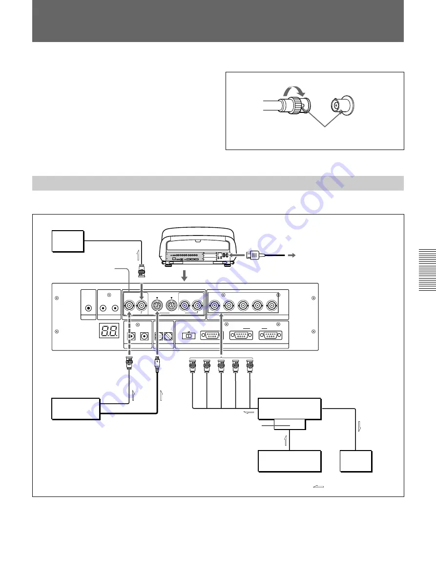
Connecting Directly to the Projector
Use the IFU-1271/1271M Signal Interface Unit.
Setting up
• Set INPUT A in the SET SETTING 1 menu
(page 35
(GB)
)
to RGB.
• Select VIDEO or S VIDEO by pressing the INPUT SELECT keys on the
remote commander.
TRIGGER
LINK
S VIDEO
OUT
IN
C IN
Y IN
VIDEO
VIDEO
R-Y/P
R
R
B-Y/P
B
G
B
SYNC/HD
VD
INPUT A
Y
CONTROL S
PLUG IN POWER
DEVICE INDEX
IN
OUT
IN
OUT
IN
OUT
REMOTE
RS-232C/422A
RS-232C RS-422A
IN
OUT
PJ COM
When making connections:
• Before connecting any cables, make sure that each
piece of equipment to be connected is turned off.
• Use cables appropriate for the equipment to be
connected.
• A loose connection may cause hum or noise.
• When disconnecting a cable, pull it out from the plug;
not the cable itself.
• Also refer to the instruction manual of the equipment
to be connected.
Connection Examples
Connecting a BNC connector:
2
Twist to the right.
1
Align the pins with the pin holes and
push the plug into the socket.
Color
monitor
to video input
Rear
AC power cord (supplied)
to a wall outlet
Video equipment
to video output
to S video output
IFU-1271/1271M
Signal Interface Unit
IFB-12/12A
signal interface
board, etc.
to RGB input
to RGB output
Computer
to RGB output
to RGB input
Color
monitor
Signal flow
R
G
B
SYNC/HD
VD
VIDEO
OUT
AC IN
VIDEO IN
S VIDEO
IN
INPUT A
*
*
For the VPH-G90E model :
IFB-G90E Video Interface Board (optional)


