3
Eingangssignal
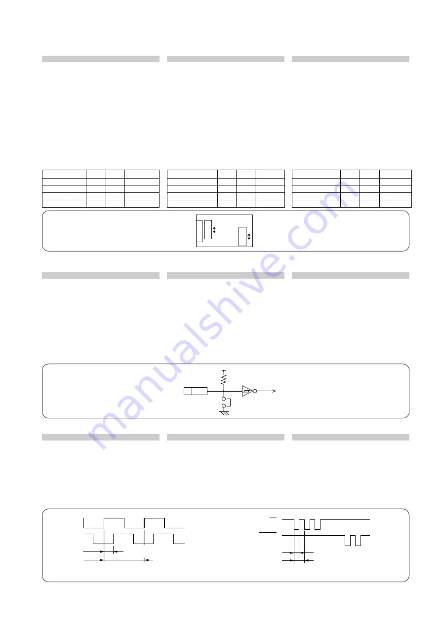
Die Schalter SW1 und SW2 an der
Leiterplatte ermöglichen die Wahl zwischen
vier Eingangsarten (A/B/Z-Signal
(Differential/TTL) und AUF/AB/Z-Signal
(Differential/TTL)).
Zum Ändern der Anfangseinstellungen von
SW1 und SW2 die zwei Halteschrauben
3
M2,6
x
19 an der Oberseite des Adapters
herausdrehen, die Abdeckung abnehmen,
und dann die Schalter einstellen. Nach der
Einstellung die Oberseite der Abdeckung
wieder mit den zwei Halteschrauben
3
M2,6
x
19 befestigen.
Eingangssignal
SW1
SW2
A/B/Z Differential
D-Seite A-Seite
A/B/Z TTL
T-Seite A-Seite
AUF/AB/Z DIfferential D-Seite U-Seite
AUF/AB/Z TTL
T-Seite U-Seite
入力信号
入力は配線板上のSW1、SW2を切替える
ことによりA/B/Z信号 (差動/TTL) または
UP/DOWN/Z 信号 (差動/TTL) の4種類が
可能です。
SW1、SW2の設定が初期設定と違う場合
は、アダプタ上部のカバー固定用ネジ
3
M2.6
x
19 (2本) にてカバーを取外し設
定してください。設定後はカバー固定用
ネジ
3
M2.6
x
19 (2本)でカバー上部を
しっかり固定します。
入力信号
S W1
S W2
A/B/Z 差動
D側
A側
初期設定
A/B/Z TTL
T側
A側
UP/DOWN/Z 差動
D側
U側
UP/DOWN/Z TTL
T側
U側
Input signal
Four types of inputs (A/B/Z signal
(differential/TTL) or UP/DOWN/Z signal
(differential/TTL)) can be selected by
switching SW1 and SW2 on the wiring
board. To change SW1 and SW2 from
the initial settings, loosen the two
3
M2.6
x
19 cover fastening screws on
top of the adaptor, remove the cover
and then set the switches. After setting
the switches, secure the top of the
cover with the two
3
M2.6
x
19 cover
fastening screws.
Input signal
SW1
SW2
A/B/Z differential
D side
A side
Initial settings
A/B/Z TTL
T side
A side
UP/DOWN/Z differential
D side
U side
UP/DOWN/Z TTL
T side
U side
配線板上面視
/
Top view of wiring board / Draufsicht der Leiterplatte
アラーム
アラームには、差動入力受信時にHighイン
ピーダンスになったことを検出するアラー
ムと、入力コネクタより入力する外部ア
ラームがあります。
通常外部アラームは無効となっていますの
で、外部アラームを接続する場合は本体内
部のJP1のショートピンを外してくださ
い。外部アラームは正論理で、Hのときア
ラーム出力されます。
Alarm
There are two alarms: the alarm that
detects high impedance when receiving
differential input and the external alarm
input from the input connector. The
external alarm is normally invalid. When
connecting the external alarm, remove
the JP1 shorting pin inside the main
unit. The external alarm is positive
logic, so the alarm is output when high.
Alarm
Es gibt zwei Alarmarten: Alarm für Erkennung
hoher Impedanz bei Empfang eines
Differential-Eingangssignals und das in den
Eingang eingespeiste externe Alarmsignal.
Da das externe Alarmsignal normalerweise
ungültig ist, muß beim Anschluß des externen
Alarms der Jumper JP1 im Inneren des
Adapters entfernt werden. Der externe Alarm
hat positive Logik, so daß der Alarm im
Zustand H ausgegeben wird.
H:
アラーム時
/ Alarm / Alarmzustand
L:
正常時
/ Normal / Normalzustand
74HC14
相当
/ Equivalent to 74HC14 / entspricht 74HC14
内部回路へ
/ To the internal circuits /
zu den internen Schaltungen
外部入力アラーム受信回路
/ External alarm reception circuit / Schaltung zum Empfang des externen Alarms
入力パルス幅
1. A/B相入力の場合
最小位相差
Tw: 200 ns
最高繰返し応答周波数
f:
1.25 MHz
2. UP/DOWN入力の場合
最小入力パルス幅
t:
100 ns
最高繰返し応答周波数
Tw: 5 MHz
Input pulse width
1. For A/B phase input:
Minimum phase difference
Tw: 200 ns
Maximum repeat response frequency
f:
1.25 MHz
2. For UP/DOWN input:
Minimum input pulse width
t:
100 ns
Maximum repeat response frequency
Tw: 5 MHz
Eingangsimpulsbreite
1. Für A/B-Phasen-Eingabe:
Minimale Phasendifferenz
Tw: 200 ns
Maximale Wiederholungs-Ansprechfrequenz
f:
1,25 MHz
2. Für AUF/AB-Eingabe:
Minimale Eingangsimpulsbreite t:
100 ns
Maximale Wiederholungs-Ansprechfrequenz
Tw: 5 MHz
1
2
UP
DOWN
t:
パルス幅
/ Pulse width / Impulsbreite
Tw:
最高繰り返し応答周波数
/
Maximum repeat response frequency /
Maximale Wiederholungs-Ansprechfrequenz
A相
/ Phase A
f:
最高繰り返し応答周波数
/
Maximum repeat response frequency /
Maximale Wiederholungs-Ansprechfrequenz
B相
/ Phase B
Tw:
最小位相差
/ Minimum phase difference /
Minimale Phasendifferenz
RL=1k
Ω
JP1
ALM
2
D-sub 9
ピン
9-pin D-sub connector
9poliger D-sub-Anschluß
SW1
SW2
D
T
A
U
D-sub 9
ピン
9-pin D-sub connector
9poliger D-sub-Anschluß
A
nfangseinstellungen
3.
Technische Daten
3.
仕様
3.
Specifications


