background image

25


PICTURE CONTROL Window

  Chapt

er

 3

  Adj

u

s

tme
nts
 and

 S

e

ttin

gs
 Us
in

g the

 S

R

X Cont

roll
er

About the items that cannot be adjusted

Items that cannot be adjusted depending on the input signal 
are not displayed in the window.

For details, see “Input Signals And Adjustable/Setting 
Items” on page 34.

Log function

Clicking the “Save Log” in the “File” menu on the menu 
bar in the Control Function Menu window saves the 
communication log between the T100 Controller and this 
projector up to the moment “Save Log” is clicked. Up to 5 
MB can be saved.

PICTURE CONTROL 
Window

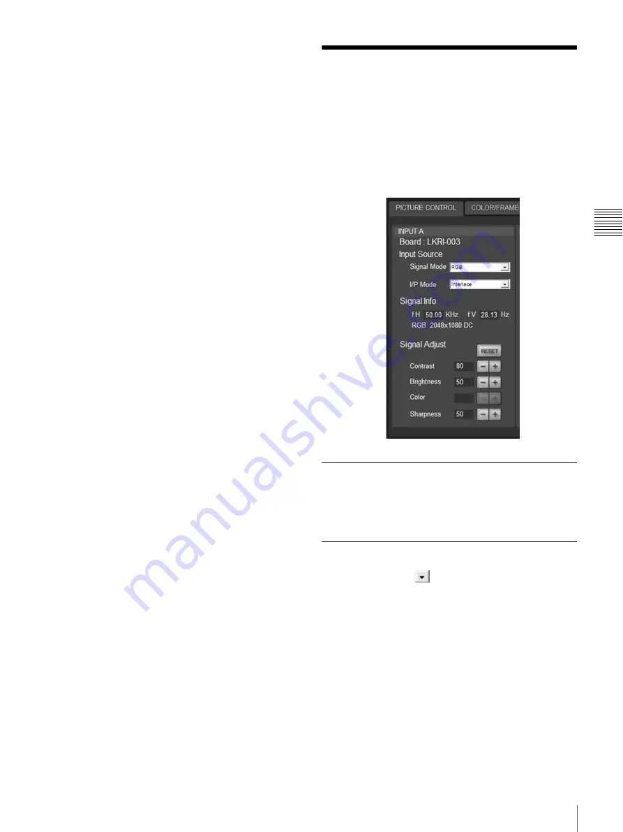
The PICTURE CONTROL window is used to select the 
input source or to adjust the picture quality.
When the screen mode is set to dual-screen mode or quad-
screen mode, the items can be independently adjusted for 
each input channel displayed on the screen.

Board

Shows the input board installed in the relative input board 
slot of the projector. 

Input Source

Signal Mode:

 Click 

 to open the drop-down list to 

select the type of signal input from equipment 
connected to the optional input board.

When the LKRI-004 or LKRI-005 is installed

Select the input signal type of progressive DVI-D 
signals.
When used in normal, select “8bit Single Full”, which 
is compatible with DVI1.0 standard and the signal 
level is Full Range compliance.
When the DTV signal is input, select “8bit Single 
Limited”, which is compatible with DVI1.0 standard 
and the signal level is Limited Range compliance.
When the 10-bit signal based on Sony’s unique 
specification is input, select “10bit Twin Full” or 
“10bit Single Full” for a signal of Full Range 

Summary of Contents for SRX-T105

Page 1: ...ealers WARNING This manual is intended for qualified service personnel only To reduce the risk of electric shock fire or injury do not perform any servicing other than that contained in the operating instructions unless you are qualified to do so Refer all servicing to qualified service personnel ...

Page 2: ...ct Adaptor 15 Connecting the Projector 16 Connecting a Computer Equipped with a DVI D Connector 16 Connecting with a Computer Equipped with an Analog RGB Connector 17 Connecting with HD SDI Equipment 17 Connecting with Component Video GBR Equipment 18 Connecting the AC Power Cord 18 Installing the SRX Controller 19 Setting the Projector 20 Displaying the SETTING Window 20 Owner Information 20 Date...

Page 3: ... 30 SERVICE Window 30 Displaying the SERVICE Window 30 WHITE BALANCE 30 REGISTRATION ADJUST 31 LAMP TIMER RESET 31 INTERPOLATION 31 COLOR SPACE CONVERTER 31 VERSION INFORMATION 31 Correcting the Color Characteristics Color Space Converter 32 Input Signals And Adjustable Setting Items 34 Chapter 4 Others Lamp Life 35 Error Messages 36 Dimensions 38 External Dimensions 38 Mounting Platform Dimension...

Page 4: ...ernal heat build up Do not place the unit on surfaces rugs blankets etc or near materials curtains draperies that may block the ventilation holes Leave space of more than 100 cm 39 3 8 inches between the wall and the projector Be aware that room heat rises to the ceiling check that the temperature near the installation location is not excessive Install the projector on the floor or hang it from th...

Page 5: ...during setting and adjustment using the optional tool kit PCAT As uniformity may change with each use it is recommended to adjust the uniformity regularly approximately once every two times the lamp is replaced For purchase of the kit contact your Sony dealer About the Optional Accessories The projection lamps of this projector are provided as optional accessories Install the lamp houses to the pr...

Page 6: ...2K image at the maximum horizontal picture element When projecting a 3840 pixel aspect ratio 16 9 image at the maximum horizontal picture element Black bands are displayed on the right and left sides When projecting a 2880 pixel aspect ratio 4 3 image at the maximum horizontal picture element Black bands are displayed on the right and left sides 2160 pixel 4096 pixel 16 9 2160 pixel 3840 pixel 128...

Page 7: ...12 5 8 inches L Center of screen Center of lens A Distance between the floor and the feet of the projector A B 320 mm 12 5 8 inches B Distance between the floor and the center of screen B A Type of lens Projection distance calculation formula when inputting a 4K 2K signal Projection distance calculation formula when inputting a 16 9 signal Projection distance calculation formula when inputting a 4...

Page 8: ... 5 6 20639 812 4 7 23605 929 1 3 L max 8056 317 1 6 8964 353 10780 424 2 5 12596 496 14412 567 2 5 16228 638 8 9 18044 710 2 5 21676 853 2 5 25308 996 3 8 28940 1139 3 8 H1 a 2373 93 3 7 2637 103 4 5 3164 124 4 7 3691 145 1 3 4219 166 4746 186 6 7 5273 207 5 8 6328 249 1 7 7383 290 2 3 8438 332 1 5 H2 b 1883 74 1 8 2092 82 3 8 2510 98 5 6 2929 115 1 3 3347 131 7 9 3766 148 1 4 4184 164 3 4 5021 19...

Page 9: ...ting a 3996 2160 pixel aspect ratio 1 85 1 image H a 2625 103 1 3 3000 118 1 9 3375 132 7 8 3750 147 2 3 4500 177 1 6 5250 206 2 3 6000 236 2 9 6750 265 3 4 7500 295 2 7 9000 354 1 3 W 4500 177 1 6 5000 196 6 7 6000 236 2 9 7000 275 3 5 8000 315 9000 354 1 3 10000 393 5 7 L min 16937 666 4 5 18792 739 5 6 22502 885 8 9 26212 1032 29922 1178 33632 1324 37342 1470 1 7 L max 31943 1257 3 5 35466 1396...

Page 10: ... 09992 H W 0 75000 a Screen height when projecting a 2880 2160 pixel aspect ratio 4 3 image W 3500 137 4 5 4000 157 1 2 4500 177 1 6 5000 196 6 7 6000 236 2 9 7000 275 3 5 8000 315 L min 18759 738 1 2 21404 842 2 3 24050 946 5 6 26695 1051 31986 1259 1 3 37277 1467 3 5 42568 1676 L max 35266 1388 2 5 40270 1585 3 7 45274 1782 4 9 50278 1979 1 2 60287 2373 1 2 70295 2767 1 2 80303 3161 5 9 H a 2625...

Page 11: ... platform is not available as an optional accessory Prepare the mounting platform shown in Mounting Platform Dimensions page 39 Attach the optional LKRA 001 exhaust duct adaptor when installing at 90 degrees angle When attaching the adaptor be sure to provide enough room for smooth exhaust flow and take care not to bend the duct Positioning the Projector towards the Screen Install the projector so...

Page 12: ...ector according to your purpose The procedure below describes how to attach the following lenses to the projector LKRL Z115 1 48 to 1 81 times zoom lens LKRL Z140 3 81 to 7 12 times zoom lens For attachment of the optional lenses not mentioned above refer to the mounting instructions supplied with each lens Handle the lens carefully as it is very heavy 1 Loosen the four screws on the lens cover wi...

Page 13: ...cing the lens cover After replacing the lens with a new one be sure to readjust the zoom and focus settings stored in each FUNCTION button Otherwise error message DATA LOAD FAILURE LENS POSITION SENSOR may appear When removing the screws from the lens to remove the lens from the projector be sure to hold the lens with your hands so that the lens does not drop When attaching the lens be careful not...

Page 14: ...put connector BNC type Connect to the output connector of an HDCAM video recorder player to input an HDTV serial digital signal b OUT HD SDI output connector BNC type Outputs a digital signal input through the IN connector when the projector is turned on Connectors on the LKRI 003 a LINK A LINK B IN HD SDI input connectors BNC type Connect to the output connectors of an HDCAM SR video recorder pla...

Page 15: ... To remove the input board loosen the screws fully and pull it out Attaching the Exhaust Duct Adaptor Attach the optional exhaust duct adaptor according to the installation situation LKRA 001 8 inch exhaust duct adaptor For details on attaching the exhaust duct adaptor refer to the Installation Instructions supplied with LKRA 001 OUT IN ...

Page 16: ... boards depending on the input signal type of the connected computer S101 on LKRI 004 board S101 and S102 on LKRI 005 board For details on setting the DIP switches refer to the Operating Instructions of LKRI 004 supplied with LKRI 004 or the Operating Instructions of LKRI 005 supplied with this projector Connecting with a computer The illustration below shows an example of connection with INPUT A ...

Page 17: ... recorder player The illustration below shows an example with the LKRI 002 attached on INPUT B When the LKRI 003 is attached to the projector select the type of signal with Signal Mode of Input Source in the PICTURE CONTROL window For Single link input select YPbPr or YPbPr FULL For Dual link input select RGB or RGB FULL For details see page 25 Note R Pr Cr B Pb Cb HD VD G Y Y IN INTER LOCK ETHERN...

Page 18: ... AC power cord that supports 8AWG 250 V 40 A or higher Follow the steps below to connect the three wire power cord to the AC IN terminal on the left side of the projector Connection of the main power and the electric wiring work should be done by qualified electricians only Do not plug the power cord into the power supply before completing the following operations 1 Remove the two screws on the te...

Page 19: ...cable clamp and the two screws removed in step 2 5 Replace the terminal cover using the two screws removed in step 1 Installing the SRX Controller Install the supplied SRX Controller on the computer used for controlling For the SRX Controller installation method refer to the Operating Instructions of this projector ...

Page 20: ...gs in each window Click the APPLY button at the lower part of each window The settings are registered Owner Information The Owner Information window is used to set information on this projector Owner Name Enter the name of an owner of the projector Organization Enter the name of an organization Projector Region Enter the region where the projector is used Location Enter the location where the proj...

Page 21: ... the used time of the projection lamps or the operating hours of the projector for maintenance to the preset addresses Report Timing Lamp Timer Reminder Presets the timing when e mail is sent for reporting the used time of the lamps Maintenance Reminder Presets the timing when e mail is sent for reporting the elapsed operating time of the projector for maintenance Re count Resets the elapsed opera...

Page 22: ... the list List box Displays the registered IP addresses of the hosts allowed to access the projector Network Block Reboot Restarts the Network CPU after the PC Communication settings complete Click the REBOOT button to restart SNMP The window is used to set up SNMP Simple Network Management Protocol SNMP sysName Enter the characters for the standard MIB sysName Contact Enter the characters for the...

Page 23: ... want to save to the computer for controlling the projector File Select and edit the filename to be saved Click to specify the file to be saved SAVE button Click to save the projector settings to the specified file Only the values of checked items will be saved Load Check the menu items projector settings which you want to load to the projector from the computer for controlling the projector The s...

Page 24: ...To reset the settings that have been adjusted Clicking the RESET button in the PICTURE CONTROL window resets all the settings of the items for Signal Adjust to their factory preset values To reset the settings of the items for Frame Adjust in the COLOR FRAME window click the RESET button in the COLOR FRAME window To register the settings that have been adjusted You can register the settings that h...

Page 25: ...o dual screen mode or quad screen mode the items can be independently adjusted for each input channel displayed on the screen Board Shows the input board installed in the relative input board slot of the projector Input Source Signal Mode Click to open the drop down list to select the type of signal input from equipment connected to the optional input board When the LKRI 004 or LKRI 005 is install...

Page 26: ... included in a 10 bit HD SDI signal data area 0 to 3 and 1020 to 1023 are blocked out 1 Data value 64 of a 10 bit HD SDI signal input is equivalent to the video level of 0 black and data value 960 equivalent to 100 white I P Mode Selects the I P conversion mode Depending on the input signal source set the mode to Interlace or PsF This item is available with the interlace or PsF signal input When t...

Page 27: ... W P 6500K 9300K CUSTOM1 CUSTOM2 and CUSTOM3 6500K is preset in CUSTOM1 to 3 settings in the factory 6500K is recommended for a normal high definition signal or RGB signal Set this item to DCI W P to project a movie source Gamma Selects a gamma correction curve The smaller the value the brighter the image Select the setting depending on the signal source 2 2 is recommended to project a normal high...

Page 28: ... the position of the picture is not adjusted correctly noise may appear in the blank portion of the screen This is not a malfunction of the projector Adjust the picture position correctly with Frame Adjust INSTALLATION Window The INSTALLATION window is used to adjust the projected picture and to change the lamp output etc LENS CONTROL Adjusts the projected picture on the screen Zoom Adjusts the si...

Page 29: ...retched to a 2 39 1 aspect ratio When you click the Off radio button the input signal is displayed without converting the aspect ratio This function is available only for projection in single screen mode LAMP POWER Adjusts the lamp power output Select it from the drop down list displayed by clicking You can reduce the lamp power to 93 86 79 72 65 58 or 51 Selecting 100 allows you to obtain the bri...

Page 30: ...click OK The default setting of the password is service The SERVICE window is displayed WHITE BALANCE Adjusts each of Gain R red G green B blue and Bias R red G green B blue to obtain the desired color temperature Use to adjust the slight color difference between the projectors when multiple projectors are used together It is recommended to perform Correcting the Color Characteristics Color Space ...

Page 31: ...rces input two picture elements each on the upper lower left and right sides may be invisible as the visible aspect ratio is 4092 2156 dots In dual screen mode with two signal sources input two picture elements each on the left and right sides are not visible and a black vertical line may appear in the center of the screen In quad screen mode with four signal sources input two picture elements eac...

Page 32: ...e measured x and y values in the respective text boxes 8 Click the CALC button 9 Output 80 red 80 green and 80 blue signals again and measure the values of x and y in the center of the screen 10Check that the difference between the measured value and the value for Target Color Gamut is within the range as shown below 80 green signal when Adobe RGB is selected within 0 01 Other than the above withi...

Page 33: ...Green1 and Blue1 in Test Pattern Select again and measure the values for x and y in the center of the screen 10Check that the difference between the measured value and the value for Target Color Gamut is within 0 005 11Click the APPLY button if the difference is within 0 005 If the difference is greater than 0 005 repeat steps 4 to 10 until the value is within 0 005 ...

Page 34: ...input signals Items that cannot be adjusted depending on the input signal are not displayed in the window Signal Adjust z Adjustable can be set Not adjustable cannot be set Frame Adjust z Adjustable can be set Not adjustable cannot be set Item Input signal Component Video GBR Computer HD SDI DVI D 4K Contrast z z z z z z Brightness z z z z z z Color z z Sharpness z z z z Item Input signal Componen...

Page 35: ... unqualified service personnel may result in explosion or fire Continuously lighting the lamp will reduce its lamp life Be sure to off the lamp for one to two hours after continuously lighting for 24 hours To replace the lamp When replacing the lamp use the optional projection lamp for replacement LKRX 110 projection lamp for SRX T110 LKRX 105 projection lamp for SRX T105 Use of any lamps other th...

Page 36: ...or intake 13 LAMP_A FAN ALERT Trouble with the sirocco fan for Lamp A or the harness is disconnected or down Check the connection of the Lamp A fan or replace the fan 14 LAMP_B FAN ALERT Trouble with the sirocco fan for Lamp B or the harness is disconnected or down Check the connection of the Lamp B fan or replace the fan 15 LAMP_A POWER SUPPLY UNIT FAN ALERT Trouble with the fan for Lamp A power ...

Page 37: ...the SY board or replace the fan with a new one 32 LOW REAL TIME CLOCK BATTERY The RTC battery BT201 for the SY 321 board should be replaced Replace the BT201 RTC battery for the SY 321 board with a new one 33 FPGA CONFIG FAILURE The internal line of the projector does not function properly Turn off the power of the projector then turn it on again 34 IIC FAILURE The internal line of the projector d...

Page 38: ... 4 498 19 5 8 Center of lens Center of gravity 1224 481 4 699 275 8 164 61 2 6 1 4 196 73 4 102 41 8 108 43 8 35 17 16 320 12 5 8 100 4 69 2 2 3 4 59 2 3 8 810 32 50 2 80 31 4 80 31 4 25 7 11 16 548 215 8 50 2 80 31 4 80 31 4 24 3 31 32 731 287 8 Center of lens Center of gravity 6 M6 depth 7 mm or less For fixing the main body Same for opposite side 4 ø10 3 mm convex Same for opposite side ...

Page 39: ...aterial Mounting platform SECC 3 2 mm 5 32 inch thickness Bolt SWCH M6 12 mm 1 2 inch for the mounting platform with 3 2 mm 5 32 inch thickness The mounting platform is symmetric with respect to a point Holes other than ø8 are clearance holes for the projector Use M6 washers and spring washers for the M6 bolts 12 when fixing the projector Notes 552 213 4 552 213 4 ...

Page 40: ...52 371 2 92 35 8 4 R7 5 5 16 116 3 45 8 142 55 8 964 38 75 4 3 10 1 13 32 822 323 8 12 1 2 36 3 17 16 15 19 32 847 7 333 8 872 343 8 927 7 365 8 952 371 2 92 35 8 4 R7 5 5 16 116 3 45 8 142 55 8 964 38 842 331 4 52 21 8 R 6 5 9 3 2 9 3 2 122 47 8 132 51 4 372 143 4 482 19 592 233 8 832 327 8 912 36 R 1 5 6 ø8 holes 12 ø13 holes 6 ø8 holes Screw hole M6 for fixing the main body Screw hole M6 for fi...

Page 41: ...lation and Maintenance Unit mm inches Unit mm inches 600 235 8 600 235 8 600 235 8 1000 393 8 2000 783 4 1000 393 8 1000 393 8 Dangerous area in case of lamp explosion 1000 393 8 1000 39 3 8 1000 393 8 Exhaust Exhaust area Dangerous area in case of lamp explosion ...

Page 42: ...Dual screen Quad screen Type of signal Horizontal size Vertical size Horizontal size Vertical size Horizontal size Vertical size VIDEO60 2880 2156 2003 1499 1440 1078 VIDEO50 2880 2146 2003 1504 1440 1073 XGA 2849 2137 2048 1536 1432 1074 SXGA1 2560 2048 2048 1638 1280 1024 SXGA2 2560 1920 2048 1536 1280 960 SXGA 2800 2100 1400 1050 1400 1050 UXGA a 2864 2148 1600 1200 WUXGA a 3437 2148 1920 1200 ...

Page 43: ...all at 90 degrees angle 11 INSTALLATION window 28 Installing Lamp Houses 12 Internet Protocol TCP IP 21 INTERPOLATION 31 L Lamp Life 35 LAMP POWER 29 LAMP SELECT 29 LAMP TIMER RESET 31 LAN 21 LENS CONTROL 28 Load 23 M Mail Report 21 Mail Server 21 Mounting Platform 11 39 N Necessary Clearance for Installation and Maintenance 41 Network 21 Network Block Reboot 22 O Optional accessories 5 Owner 20 O...

Page 44: ...Sony Corporation ...

Reviews: