17
Connecting the Projector
Cha
p
te
r 2
In
s
tallat
io
n
a
nd Conn
ec
ti
ons
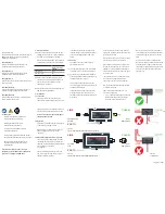
Connecting with a Computer
Equipped with an Analog RGB
Connector
Attach the optional LKRI-001 analog input board to the
input board attachment part on the projector, and connect
with a computer.
Select “RGB” in “Signal Mode” of “Input Source” in the
PICTURE CONTROL window.
For details, see page 25.
Connecting with HD-SDI Equipment
Attach the optional LKRI-002 HD-SDI (4:2:2) or LKRI-
003 HD-SDI (4:4:4) input board to the input board
attachment part, and connect the HDCAM recorder/player.
The illustration below shows an example with the LKRI-
002 attached on INPUT B.
When the LKRI-003 is attached to the projector, select the
type of signal with “Signal Mode” of “Input Source” in the
PICTURE CONTROL window. For Single-link input,
select “YPbPr” or “YPbPr FULL”. For Dual-link input,
select “RGB” or “RGB FULL”.
For details, see page 25.
Note
R(Pr/Cr)
B(Pb/Cb)
HD
VD
G(Y/Y)
IN
INTER LOCK ETHERNET
RS232C
OUT
IN
OUT
AUX
DVI-D
R/G/B/HD/VD
connectors
Monitor cable (not supplied)
Computer
to monitor output
Left side
Note
SRW-5000
HD DIGITAL VIDEO CASSETTE RECORDER
INTER LOCK ETHERNET
RS232C
IN
OUT
AUX
DVI-D
IN connector
HD-SDI connecting
cable (not supplied)
HDCAM recorder/player, etc.
Left side
to HD-SDI output
IN connector
Summary of Contents for SRX-T105
Page 44: ...Sony Corporation ...


