2-25
SRX-R320
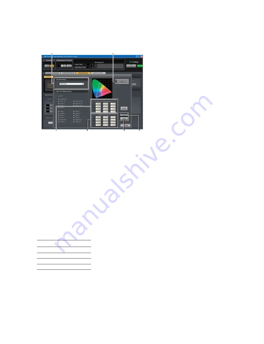
“Input Color
Measurement” column
“Target Color
Gamut” column
[RESET]
button
[CALC]
button
[APPLY]
button
“COLOR SPACE” menu
Fig. 2-5j
12. Click the
[ADJUST]
button in the “COLOR SPACE CONVERTER” menu.
The “COLOR SPACE” window is displayed.
13. Select “Virtual White” in the “COLOR SPACE” menu.
n
When “COLOR SPACE” is not available, input a video signal.
14. Click the
[RESET]
button
fi
rst, and then click the
[APPLY]
button.
15. Change the W values of “Target Color Gamut” to x = 0.314, and y = 0.351.
16. Reproduce the “Red-1”, “Green-1”, “Blue-1” and “Gray-8” of Sony Color Patch signal from
LMT-300 by Screen Management Controller.
Then, measure the x and y values respectively.
17. Enter the x and y values in Input Color Measurement on the “COLOR SPACE” window.
18. Click the
[CALC]
button
fi
rst, and then click the
[APPLY]
button.
19. Reproduce the “Red-1”, “Green-1”, “Blue-1” and Gray-8 of Sony Color Patch signal from LMT-300
by Screen Management Controller.
Then, measure the x and y values respectively, and compare the results with the following DCI speci-
fi
cations within an error range of 0.006.
x
y
Red-1 0.680 0.320
Green-1 0.265 0.690
Blue-1 0.150 0.060
Gray-8 0.314 0.351
n
If the speci
fi
cations are not satis
fi
ed, perform steps 9, 10, and 14 to 18 again.
20. Reproduce “Gray-10” from LMT-300 and adjust the lamp power in the “LAMP POWER” menu so
that the luminance is 14 ft-L.
n
If the luminance of 16 ft-L or 14 ft-L is not ensured, set the lamp power setting to 100% and perform
adjustment in the maximum luminance state.
Summary of Contents for SRX-R320
Page 1: ...DIGITAL CINEMA PROJECTOR SRX R320 INSTALLATION MANUAL 1st Edition ...
Page 4: ......
Page 6: ......
Page 44: ...1 38 SRX R320 1 14 Dimensions Front Left Exhaust Barycentric position Barycentric position ...
Page 46: ......
Page 125: ......
Page 126: ...Sony Corporation SRX R320 SY E 9 968 659 01 Printed in Japan 2009 10 22 2009 ...


