background image

1-5

20

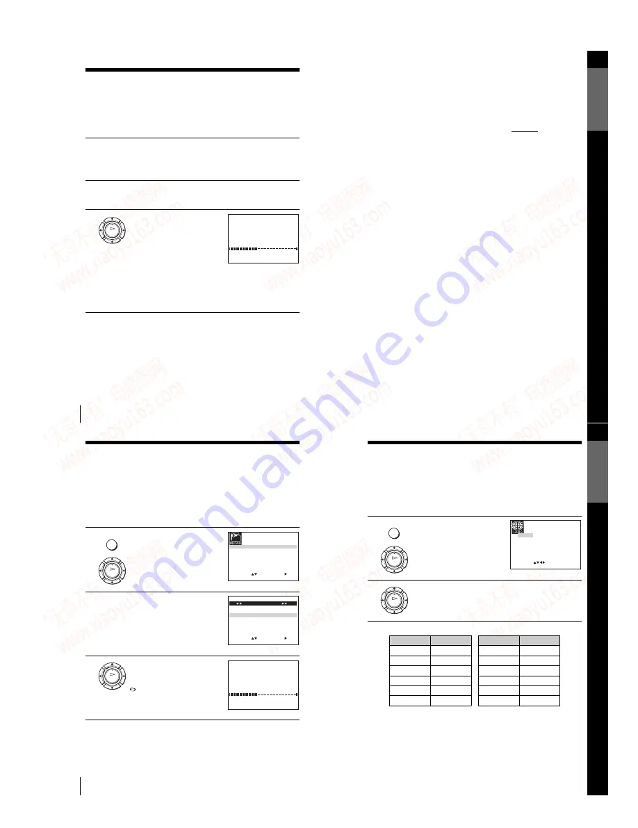
Setting up the VCR with the Auto Set Up function

Step 4 : Setting up the VCR with the Auto 

Set Up function

Before using the VCR for the first time, set up the VCR using the Auto Set Up 
function.  With this function, you can set the TV channels, guide channels for the 
VIDEO Plus+* system, and VCR clock automatically.

To cancel the Auto Set Up function

Press MENU.

To change the RF channel

If the picture does not appear clearly on the TV, change the RF channel on 
the VCR and TV.  Select INSTALLATION from the menu, then press 

M

/

m


to highlight VCR OUTPUT CH and press 

,

.  Select the RF channel by 

pressing the 

M

/

m

 buttons.  Then, tune the TV to the new RF channel so that 

a clear picture appears.

1

Turn on your TV and set it to the video channel.

If your TV does not have a Scart (EURO-AV) connector, tune the 
TV to channel 21 (the initial RF channel for this VCR).  Refer to 
your TV’s manual for TV tuning instructions.  If the picture does not 
appear clearly, see “To change the RF channel” on page 20.

2

Connect the mains lead to the mains.

The VCR automatically turns on, and the message for the Auto Set 
Up function appears.

3

Press OK.

The VCR starts searching for all of 
the receivable channels and presets 
them in the appropriate order for 
your local area.

If you want to change the order of 
the channels or disable unwanted 
programme positions, see 
“Changing/disabling programme 
positions” on page 27.

After the search or download is complete, the current time appears 
for any stations that transmit a time signal.  If the time does not 
appear, set the clock manually.  See “Setting the clock” on page 32.

OK

M E N U

:

P L E A S E   W A I T

A U T O   S E T   U P

4 0 %

E X I T

21

Setting up the VCR with the Auto Set Up function

Ge
tting Star

te

d

Notes

• Whenever you operate the Auto Set Up function, some of the settings 

(VIDEO Plus+, timer, etc.) will be reset.  If this happens, you have to set them 
again.

• Auto preset starts automatically only when you plug in the mains lead for the first 

time after you purchase the VCR.

• If you want to use the Auto Set Up function again, press MENU, then press 

M

/

m

/

<

/

,

 to highlight INSTALLATION and press OK.  Press 

M

/

m

 to highlight 

AUTO SET UP, then repeat the procedure in step 3.

• Auto preset can be performed by pressing 

x

 (stop) on the VCR continuously for 5 

seconds or more with no tape inserted.

* not  available on SLV-SE240G

22

Downloading the TV tuner’s preset data (not available on SLV-SE240G/I)

Downloading the TV tuner’s preset data 

(not available on SLV-SE240G/I)

You can download your TV tuner’s preset data to the VCR and tune the VCR 
according to that data using the SMARTLINK connection.

Before you start

• Turn on the VCR and the TV.
• Set the TV to the video channel.
• Refer to “Index to parts and controls” for button locations.

1

Press MENU, then press 

M

/

m

/

<

/

,

 to highlight INSTALLATION 

and press OK.

2

Press 

M

/

m

 to highlight 

SMARTLINK, then pres

,

.

3

Press 

M

/

m

 to highlight TV CH 

DOWNLOAD, then press 

,

.  

Press 

,

 again.  The Preset 

Download function starts and the 

 indicator flashes in the display 

window during download.

MENU

OK

S E T

M E N U

:

:

O K

:

E N D

S E L E C T

A U T O   S E T   U P
M A N U A L   S E T   U P
S M A R T L I N K

2 1

:

V C R   O U T P U T   C H

:

E X I T

E X I T

M E N U

:

S E T

:

O K

:

E N D

S E L E C T

S M A R T L I N K

T V   D I R E C T   R E C O R D   :   O N

T V   C H   D O W N L O A D

:

OK

T V   C H   D O W N L O A D

4 0 %

O K

:

E N D

E X I T

M E N U

:

P L E A S E   W A I T

23

Selecting a language

Ge
tting Star

te

d

Selecting a language

If you prefer an on-screen language other than English, use the on-screen display to 
select another language.

Before you start…

• Turn on the VCR and the TV.
• Set  the TV to the video channel.
• Refer to “Index to parts and controls” for button locations.

The abbreviations of the languages are as follows:

1

Press MENU, then press 

M

/

m

/

<

/

,

 to highlight LANGUAGE SET 

and press OK.

2

Press 

M

/

m

/

<

/

,

 to highlight the abbreviation of the desired 

language from the table below, then press OK.

MENU

OK

E X I T

M E N U

:

O K

:

S E T

S E L E C T

:

G B
E S
N L
F I

D E
I T
S E
G R

F R
P T
D K
T R

OK


Abbreviation

Language

GB

English

ES

Spanish

NL

Dutch

FI

Finnish

DE

German

IT

Italian

SE

Swedish

GR

Greek

FR

French

PT

Portuguese

DK

Danish

TR

Turkish

Abbreviation

Language

www. xiaoyu163. com

QQ 376315150

9

9

2

8

9

4

2

9

8

TEL 13942296513

9

9

2

8

9

4

2

9

8

0

5

1

5

1

3

6

7

3

Q

Q

TEL  13942296513  QQ  376315150  892498299 

TEL  13942296513  QQ  376315150  892498299 

http://www.xiaoyu163.com

http://www.xiaoyu163.com

Summary of Contents for RMT-V405

Page 1: ...to R69 CATV S1 to S41 S01 to S05 RF output signal SE240D SE240G SE240I SE440K SE640D SE640E SE640N UHF channels 21 to 69 Aerial out 75 ohm asymmetrical aerial socket Tape speed SE240B SP PAL 23 39 mm s recording playback NTSC 33 35 mm s playback only SECAM 23 39 mm s recording playback MESECAM 23 39 mm s playback only LP NTSC 16 67 mm s playback only SECAM 11 70 mm s recording playback MESECAM 11 ...

Page 2: ... mm s recording playback NTSC 16 67 mm s playback only SECAM 11 70 mm s recording playback MESECAM 11 70 mm s playback only EP NTSC 11 12 mm s playback only Maximum recording playback time 10 hrs in LP mode with E300 tape Rewind time Approx 1 min with E180 tape Inputs and outputs LINE 1 EURO AV 21 pin Video input pin 20 Audio input pins 2 and 6 Video output pin 19 Audio output pins 1 and 3 LINE 2 ...

Page 3: ...ake Ass y Removal 2 12 2 3 13 Lever Brake S T Ass y Removal 2 13 2 3 14 Gear Idle Ass y Removal 2 13 2 3 15 Disk S T Reel Removal 2 14 2 3 16 Holder Clutch Ass y Removal 2 14 2 3 17 Lever Up Down Ass y Gear Center Ass y Removal 2 15 2 3 18 Guide Cassette Door Removal 2 15 2 3 19 Lever Unit Pinch Ass y Plate Joint Spring Pinch Drive Removal 2 16 2 3 20 Lever 9 Guide Ass y Removal 2 16 2 3 21 FE Hea...

Page 4: ...nloading position rotate holder Clutch counterclockwise after inserting screwdriver in the frame s bottom hole in order to wind the unwound tape Refer to Fig 3 If you rotate Gear Worm 1 continuously when tape is unwinding you may cause tape contamination by grease and tape damage Be sure to wind the unwound tape with the unit in the horizontall position 3 Rotate Gear Worm 1 clockwise using a screw...

Page 5: ...om a cold to a warm location moisture may condense inside the VCR and cause damage to the video head and tape When you first install the unit or when you move it from a cold to a warm location wait for about three hours before operating the unit Caution Television programmes films video tapes and other materials may be copyrighted Unauthorized recording of such material may be contrary to the prov...

Page 6: ...to parts and controls N TV VIDEO remote control switch 12 O 1 on standby switch 13 14 P AUDIO MONITOR button 1 3 14 Q t TV VIDEO button 13 17 38 R CLEAR button 35 58 S INPUT SELECT button 37 51 70 T PROG programme buttons 1 13 37 U y SLOW button 53 V 2 button 53 W index search buttons 3 62 X TIMER button 50 1 The H play AUDIO MONITOR number 5 and PROG buttons have a tactile dot 3 not available on ...

Page 7: ...he remote sensor to direct light from the sun or lighting apparatus Doing so may cause a malfunction Some buttons may not work with certain Sony TVs 2 not available on SLV SE240G I Select the sound 2 AUDIO MONITOR Call up the on screen display DISPLAY Switch to from wide mode of a Sony wide TV For other manufactures wide TVs wide To Press 15 Setting up the remote commander Getting Started Code num...

Page 8: ...e VCR s on screen display automatically by pressing MENU on the remote commander One Touch Timer When the VCR is turned on you can turn on the TV set the TV to the video channel and display the timer recording menu the TIMER PROGRAMMING menu or the VIDEOPLUS menu automatically by pressing TIMER on the remote commander You can set which timer recording menu is displayed using TIMER METHOD in the EA...

Page 9: ... function again press MENU then press M m to highlight INSTALLATION and press OK Press M m to highlight AUTO SET UP then repeat the procedure in step 3 Auto preset can be performed by pressing x stop on the VCR continuously for 5 seconds or more with no tape inserted not available on SLV SE240G 22 Downloading the TV tuner s preset data not available on SLV SE240G I Downloading the TV tuner s prese...

Page 10: ...setting channels If the picture is not clear If the picture is not clear you may use the Manual Fine Tuning MFT function After step 4 press M m to select MFT Press to get a clear picture then press MENU to exit the menu Tip The VCR must receive channel information for station names to appear automatically Note When adjusting MFT the menu may become difficult to read due to interference from the pi...

Page 11: ...TV STATION TABLE 5 4 3 2 1 3 3 2 2 0 7 I C A J D A K E B PR CH NAME CLEAR DELETE MENU continued 30 Changing disabling programme positions Changing the station names You can change or enter the station names up to 4 characters The VCR must receive channel information for station names to appear automatically Before you start Turn on the VCR and the TV Set the TV to the video channel Refer to Index ...

Page 12: ... Additional tasks 1 Turn on your TV and set it to the video channel 2 Insert a tape The VCR turns on and starts playing automatically if you insert a tape with its safety tab removed 3 Press H play When the tape reaches the end it will rewind automatically To Do this Stop play Press x stop Pause play Press X pause Resume play after pause Press X pause or H play Fast forward the tape Press M fast f...

Page 13: ...n the USER SET menu is set according to the tape type you use see page 66 To watch another TV programme while recording 5 Press z REC to start recording The recording indicator lights up in the display window 1 Press t TV VIDEO to turn off the VIDEO indicator in the display window 2 Select another programme position on the TV REC Recording indicator SE240G I 6 1 4 REMAIN 2 0 0 0 2 Remaining time T...

Page 14: ...ct number 3 Press OK The date start and stop times programme position tape speed and PDC setting appear on the TV screen If appears in the PR programme column this may happen for local broadcasts you have to set the appropriate programme position manually Press M m to select the desired programme position To record from other equipment connected to one or more of the LINE inputs press INPUT SELECT...

Page 15: ...o select the recording pattern Each time you press m the indication changes as shown below Press M to change the indication in reverse order today t DLY Monday to Sunday t W SA every Saturday t W SU every Sunday t 1 month later t dates count down t today 2 Set the date start and stop times programme position tape speed and PDC function 1 Press to select each item in turn 2 Press M m to set each it...

Page 16: ...ack Dial 55 Setting the recording duration time Additional Operations Setting the recording duration time After you have started recording in the normal way you can have the VCR stop recording automatically after a specified duration Before you start Refer to Index to parts and controls for button locations To extend the duration Press z REC repeatedly to set a new duration time To cancel the dura...

Page 17: ...rogramme 2 60 Recording stereo and bilingual programmes not available on SLV SE240G I Recording stereo and bilingual programmes not available on SLV SE240G I In the NICAM system This VCR receives and records stereo and bilingual programmes based on the NICAM system NICAM appears on the TV screen When a stereo or bilingual programme is received the STEREO indicator appears in the display window To ...

Page 18: ... search depending on the direction where your desired programme is located Each time you press the button the number increases or decreases up to 20 respectively 4 The VCR starts searching and playback starts automatically from that point INDEX SCAN BB INDEX SEARCH BB 0 2 63 Searching using the index function not available on SLV SE240G I Additional Operations Notes No index signal will be added w...

Page 19: ...en pressing the TIMER button STANDARD to display the TIMER PROGRAMMING menu when pressing the TIMER button VIDEOPLUS to display the VIDEOPLUS menu when pressing the TIMER button For details see pages 46 and 50 Menu option Set this option to 68 Connecting to a VCR or stereo system Editing Connecting to a VCR or stereo system How to connect to record on this VCR Connect the line outputs of the other...

Page 20: ... with the VCR Reset the RF channel output of your VCR see page 20 Adjust the tracking with the PROGRAM buttons on the VCR The video heads are dirty see the last page of Troubleshooting Clean the video heads using a Sony video head cleaning cassette If a Sony cleaning cassette is not available in your area have the heads cleaned at your nearest Sony service facility a standard service charge will b...

Page 21: ...26 Monaural 61 N NICAM broadcasts 60 Normal audio track 61 O Optional setting 66 P PDC Programme Delivery Control 48 Playback 34 at various speeds 53 selecting the sound 61 slow motion 53 Power save 65 Preset download 22 Presetting channels 24 R Recording 37 bilingual programmes 60 duration time 55 saving 39 stereo programmes 60 timer setting 50 using the VIDEOPlus system 46 what you are watching ...

Page 22: ...INET TOP 2 Lift up the Cabinet Top in the direction of arrow by releasing the Hook 1 REMOVE 2 SCREWS 1 RELEASE 2 SNAPFITS 2 Lift up the Bottom Cover in the direction of arrow www xiaoyu163 com QQ376315150 9 9 2 8 9 4 2 9 8 TEL 13942296513 9 9 2 8 9 4 2 9 8 0 5 1 5 1 3 6 7 3 Q Q TEL 13942296513 QQ 376315150 892498299 TEL 13942296513 QQ 376315150 892498299 http www xiaoyu163 com http www xiaoyu163 c...

Page 23: ...TOM VIEW ASS Y PANEL FRONT Disconnect the CN701 from the Ass y PCB Main and then lift the Ass y PCB Jack up CN701 CN703 CN702 CN704 CN705 www xiaoyu163 com QQ376315150 9 9 2 8 9 4 2 9 8 TEL 13942296513 9 9 2 8 9 4 2 9 8 0 5 1 5 1 3 6 7 3 Q Q TEL 13942296513 QQ 376315150 892498299 TEL 13942296513 QQ 376315150 892498299 http www xiaoyu163 com http www xiaoyu163 com ...

Page 24: ...ASS Y DECK 9 ASS Y MAIN PCB 6 FLAT CABLE 3 4 SCREWS 5 FLAT CABLE 4 FLAT CABLE www xiaoyu163 com QQ376315150 9 9 2 8 9 4 2 9 8 TEL 13942296513 9 9 2 8 9 4 2 9 8 0 5 1 5 1 3 6 7 3 Q Q TEL 13942296513 QQ 376315150 892498299 TEL 13942296513 QQ 376315150 892498299 http www xiaoyu163 com http www xiaoyu163 com ...

Page 25: ... 4 HOLDER FL CASSETTE ASS Y 5 LEVER FL DOOR 6 SLIDER FL DRIVE Fig 2 6 Top parts Location 1 www xiaoyu163 com QQ376315150 9 9 2 8 9 4 2 9 8 TEL 13942296513 9 9 2 8 9 4 2 9 8 0 5 1 5 1 3 6 7 3 Q Q TEL 13942296513 QQ 376315150 892498299 TEL 13942296513 QQ 376315150 892498299 http www xiaoyu163 com http www xiaoyu163 com ...

Page 26: ...ASS Y 8 DISK S REEL 9 LEVER S BRAKE ASS Y q GEAR IDLE qa LEVER IDLE qs LEVER T BRAKE ASS Y qd DISK T REEL Fig 2 7 Top Parts Location 2 www xiaoyu163 com QQ376315150 9 9 2 8 9 4 2 9 8 TEL 13942296513 9 9 2 8 9 4 2 9 8 0 5 1 5 1 3 6 7 3 Q Q TEL 13942296513 QQ 376315150 892498299 TEL 13942296513 QQ 376315150 892498299 http www xiaoyu163 com http www xiaoyu163 com ...

Page 27: ...ADING DRIVE 7 LEVER S LOAD ASS Y 8 HOLDER CLUTCH ASS Y 9 BELT PULLEY q SLIDER CAM Fig 2 8 Bottom Parts Location www xiaoyu163 com QQ376315150 9 9 2 8 9 4 2 9 8 TEL 13942296513 9 9 2 8 9 4 2 9 8 0 5 1 5 1 3 6 7 3 Q Q TEL 13942296513 QQ 376315150 892498299 TEL 13942296513 QQ 376315150 892498299 http www xiaoyu163 com http www xiaoyu163 com ...

Page 28: ...he Holder FL Cassette Ass y 1 is taken out completely Note Be sure to insert Lever FL Cassette R 2 in the direction of A to prevent separation and breakage of the Lever FL Cassette R 2 at disassembling and reassembling Fig 2 9 Holder FL Cassette Ass y Removal 2 3 2 Lever FL Door Removal 1 Release the Hook 2 and Remove the Lever FL Door 1 in the direction of arrow A Fig 2 10 Lever FL Door Removal 1...

Page 29: ... to Timing point Fig 2 11 Slider FL Drive Removal Fig 2 12 Gear FL Cam Gear Worm 2 3 4 Lever FL Arm Ass y Removal 1 Push the hole A in the direction of arrow B use the pin about Dia 2 5 2 Pull out the Lever FL Arm Ass y 1 from the Boss of Main Base 3 Remove the Lever FLArmAss y 1 in the direction of arrow C Fig 2 13 Lever FL Arm Ass y Removal 1 GEAR FL CAM GEAR WORM WHEEL POST TIMING POINT 1 LEVER...

Page 30: ...he Drum connecting part of Cable Flat 1from Connector Waffer 2 2 Remove the Loading Motor connecting part of Cable Flat 1 from Connector Waffer 3 Fig 2 15 Cable Flat Removal www xiaoyu163 com QQ376315150 9 9 2 8 9 4 2 9 8 TEL 13942296513 9 9 2 8 9 4 2 9 8 0 5 1 5 1 3 6 7 3 Q Q TEL 13942296513 QQ 376315150 892498299 TEL 13942296513 QQ 376315150 892498299 http www xiaoyu163 com http www xiaoyu163 co...

Page 31: ...et Gear 2 3 Remove the Gear Joint 2 3 4 Remove the Gear Joint 1 4 Assembly 1 Be sure to align dot mark of Gear Joint 1 1 with dot mark of Gear Joint 2 2 as shown Fig 2 18 Refer to Timing point1 2 Confirm the Timing Point 2 of the Gear Joint 2 2 and Slider Cam 3 Fig 2 17 Bracket Gear Gear Joint 1 2 Removal Fig 2 18 Gear Joint 1 2 Assembly www xiaoyu163 com QQ376315150 9 9 2 8 9 4 2 9 8 TEL 13942296...

Page 32: ...2 Insert the Pin A B C D into the Slider Cam 3 hole 3 Be sure to align dot of Lever Load T 1 and dot of Gear Loading Drive 4 Refer to Timing Point 2 4 Aline dot of Gear Loading drive 4 with mark of Slider Cam 3 as shown in drawing Refer to Timing Point 3 Fig 2 20 Gear Loading Drive Slider Cam Lever Load S T Ass y Assembly 1 GEAR LOADING DRIVE 5 LINK LOAD S 3 LEVER LOAD S 4 LEVER LOAD T 6 LINK LOAD...

Page 33: ...arrow A 4 Lift the Lever Tension Ass y 2 Band brake Ass y 3 Note 1 When replacing the LeverTensionAss y 2 be sure to apply Grease on the post 2 Take care not to touch stain on the felt side and not to be folder and broken Band brake Ass y 3 After Lever Tension Ass y seated Rotate stopper of Main Base to the Mark B Fig 2 22 Lever Tension Ass y Band Brake Ass y Removal 1 LEVER PINCH DRIVE 2 LEVER TE...

Page 34: ...s y Removal 1 Push the Lever Idle 1 in the direction of arrow A B 2 Lift the Lever Idle 1 Assembly 1 Apply oil in two Bosses of Lever Idle 1 2 Assemble the Gear Idle 2 with the Lever Idle 1 Note When replacing the Gear Idle 2 be sure to add oil in the boss of Lever Idle 1 Fig 2 24 Gear Idle Ass y Removal 1 LEVER S BRAKE ASS Y 2 LEVER T BRAKE ASS Y 3 SPRING BRAKE HOOK B HOOK C HOOK A 2 GEAR IDLE 2 ...

Page 35: ...t insert Holder Clutch Ass y into post center with dead force and Rotate it smoothly Be sure to confirm that spring is in the slit of Gear CenterAss y as shown in detail B Fig 2 26 Holder Clutch Ass y Removal 1 DISK S REEL 2 DISK T REEL 1 WASHER SLIT 2 HOLDER CLUTCH ASS Y DETAIL A BAD SPRING GOOD BAD SPRING GOOD DETAIL B www xiaoyu163 com QQ376315150 9 9 2 8 9 4 2 9 8 TEL 13942296513 9 9 2 8 9 4 2...

Page 36: ...to confirm that Ring of the Gear Center Ass y 2 is in the Guide of the Lever Up Down Ass y 1 after finishing assembly of Lever Up Down Ass y 1 and Gear Center Ass y 2 Fig 2 27 Lever Up Down Ass y Removal Fig 2 28 Lever Up Down Ass y Removal 2 3 18 Guide Cassette Door Removal 1 Lift the Hook A 2 Rotate the Guide Cassette Door 1 in the direction of arrow Note After reinstalling the Guide Cassette Do...

Page 37: ...Removal 1 Remove the Spring 9 Guide 1 2 Lift the Spring 9 Guide Ass y 2 in the direction of arrow A Note 1 Take extreme care not to get grease on the tape Guide Post 2 After reinstalling check the bottom side of the Post 9 Guide to the top side of Main Base Fig 2 31 Lever 9 Guide Ass y Removal 3 SPRING PINCH DRIVE 1 LEVER UNIT PINCH ASS Y 2 PLATE JOINT 1 SPRING 9 GUIDE 2 LEVER 9 GUIDE ASS Y A B ww...

Page 38: ...f ACE Head Ass y 2 2 Remove the screw 1 3 Lift the ACE Head Ass y 2 Fig 2 33 ACE Head Removal 1 FE HEAD 1 SCREW 2 HEAD ACE ASS Y www xiaoyu163 com QQ376315150 9 9 2 8 9 4 2 9 8 TEL 13942296513 9 9 2 8 9 4 2 9 8 0 5 1 5 1 3 6 7 3 Q Q TEL 13942296513 QQ 376315150 892498299 TEL 13942296513 QQ 376315150 892498299 http www xiaoyu163 com http www xiaoyu163 com ...

Page 39: ...y 3 2 Tighten the 1 Screw 1 3 Match the Plate Ground Deck 2 to the Hole of Base Main 4 Tighten the other 2 Screws 1 Note 1 Take care not to touch the Cylinder Ass y 3 and the tape guide post at reinstalling 2 When reinstalling Don t push down too much on Screw Driver Fig 2 35 Plate Ground Deck Cylinder Ass y Removal 1 SLIDER S ASS Y 2 SLIDER T ASS Y 1 3 SCREWS 2 PLATE GROUND DECK 3 CYLINDER ASS Y ...

Page 40: ...ghten the 3 Screws 2 in the direction of arrow as shown detail drawing 3 Assemble the Damper Capstan 1 Note After tightening screws check if there is gap between the head of screws and the top side of Main Base There should have no gap between the head of screws and the top side of Main Base After reinstalling adjusting the tape transport system again Fig 2 37 Motor Capstan Ass y Removal 1 BELT PU...

Page 41: ...nloading rotate holder Clutch counterclockwise after inserting screw driver in the hole of frame s bottom in order to wind the unwinded tape Refer to Fig 2 41 If you rotate Gear Worm 1 continuously when tape is in state of unwinding you may cause a tape contamination by grease and tape damage Be sure to wind the unwinded tape in the state of set horizently 3 Rotate Gear Worm 1 clockwise using scre...

Page 42: ...VE TENSION POST CENTER LEVER IDLE BOSS 2Point CAPSTAN MOTOR PULLEY O O O O O BELT PULLEY O O O O O O O HOLDER CLUTCH ASS Y O O O O O O O O O GEAR CENTER ASS Y O O O O O O O O O GEAR IDLE 2Point O O O O O O O O O LOADING MOTOR O O O O O O O O O BAND BRAKE ASS Y O O O O O O O O O BRAKE T ASS Y O O O O O O O O O S Y S T E M Periodic time of applying oil Apply oil after cleaning The excessive applying...

Page 43: ...0E SE640N SLV SE240B SE240D SE240G SE240I SE440K SE640B SE640D SE640E SE640N w w w x i a o y u 1 6 3 c o m Q Q 3 7 6 3 1 5 1 5 0 9 9 2 8 9 4 2 9 8 T E L 1 3 9 4 2 2 9 6 5 1 3 9 9 2 8 9 4 2 9 8 0 5 1 5 1 3 6 7 3 Q Q TEL 13942296513 QQ 376315150 892498299 TEL 13942296513 QQ 376315150 892498299 http www xiaoyu163 com http www xiaoyu163 com ...

Page 44: ...o y u 1 6 3 c o m Q Q 3 7 6 3 1 5 1 5 0 9 9 2 8 9 4 2 9 8 T E L 1 3 9 4 2 2 9 6 5 1 3 9 9 2 8 9 4 2 9 8 0 5 1 5 1 3 6 7 3 Q Q TEL 13942296513 QQ 376315150 892498299 TEL 13942296513 QQ 376315150 892498299 http www xiaoyu163 com http www xiaoyu163 com ...

Page 45: ...1 6 3 c o m Q Q 3 7 6 3 1 5 1 5 0 9 9 2 8 9 4 2 9 8 T E L 1 3 9 4 2 2 9 6 5 1 3 9 9 2 8 9 4 2 9 8 0 5 1 5 1 3 6 7 3 Q Q TEL 13942296513 QQ 376315150 892498299 TEL 13942296513 QQ 376315150 892498299 http www xiaoyu163 com http www xiaoyu163 com ...

Page 46: ...SIDE w w w x i a o y u 1 6 3 c o m Q Q 3 7 6 3 1 5 1 5 0 9 9 2 8 9 4 2 9 8 T E L 1 3 9 4 2 2 9 6 5 1 3 9 9 2 8 9 4 2 9 8 0 5 1 5 1 3 6 7 3 Q Q TEL 13942296513 QQ 376315150 892498299 TEL 13942296513 QQ 376315150 892498299 http www xiaoyu163 com http www xiaoyu163 com ...

Page 47: ...SIDE w w w x i a o y u 1 6 3 c o m Q Q 3 7 6 3 1 5 1 5 0 9 9 2 8 9 4 2 9 8 T E L 1 3 9 4 2 2 9 6 5 1 3 9 9 2 8 9 4 2 9 8 0 5 1 5 1 3 6 7 3 Q Q TEL 13942296513 QQ 376315150 892498299 TEL 13942296513 QQ 376315150 892498299 http www xiaoyu163 com http www xiaoyu163 com ...

Page 48: ...model 4 21 4 10 Input Output 2 Scart Jack 4 23 4 11 Function Hi Fi model 4 25 4 2 4 1 SLV SE240B SE240D SE240G SE240I SE440K SE640B SE640D SE640E SE640N Hi Fi model SE640B SE640D SE640E SE640N w w w x i a o y u 1 6 3 c o m Q Q 3 7 6 3 1 5 1 5 0 9 9 2 8 9 4 2 9 8 T E L 1 3 9 4 2 2 9 6 5 1 3 9 9 2 8 9 4 2 9 8 0 5 1 5 1 3 6 7 3 Q Q TEL 13942296513 QQ 376315150 892498299 TEL 13942296513 QQ 376315150 8...

Page 49: ...3 4 4 w w w x i a o y u 1 6 3 c o m Q Q 3 7 6 3 1 5 1 5 0 9 9 2 8 9 4 2 9 8 T E L 1 3 9 4 2 2 9 6 5 1 3 9 9 2 8 9 4 2 9 8 0 5 1 5 1 3 6 7 3 Q Q TEL 13942296513 QQ 376315150 892498299 TEL 13942296513 QQ 376315150 892498299 http www xiaoyu163 com http www xiaoyu163 com ...

Page 50: ...6 3 c o m Q Q 3 7 6 3 1 5 1 5 0 9 9 2 8 9 4 2 9 8 T E L 1 3 9 4 2 2 9 6 5 1 3 9 9 2 8 9 4 2 9 8 0 5 1 5 1 3 6 7 3 Q Q TEL 13942296513 QQ 376315150 892498299 TEL 13942296513 QQ 376315150 892498299 http www xiaoyu163 com http www xiaoyu163 com ...

Page 51: ... 3 c o m Q Q 3 7 6 3 1 5 1 5 0 9 9 2 8 9 4 2 9 8 T E L 1 3 9 4 2 2 9 6 5 1 3 9 9 2 8 9 4 2 9 8 0 5 1 5 1 3 6 7 3 Q Q TEL 13942296513 QQ 376315150 892498299 TEL 13942296513 QQ 376315150 892498299 http www xiaoyu163 com http www xiaoyu163 com ...

Page 52: ... y u 1 6 3 c o m Q Q 3 7 6 3 1 5 1 5 0 9 9 2 8 9 4 2 9 8 T E L 1 3 9 4 2 2 9 6 5 1 3 9 9 2 8 9 4 2 9 8 0 5 1 5 1 3 6 7 3 Q Q TEL 13942296513 QQ 376315150 892498299 TEL 13942296513 QQ 376315150 892498299 http www xiaoyu163 com http www xiaoyu163 com ...

Page 53: ... 1 6 3 c o m Q Q 3 7 6 3 1 5 1 5 0 9 9 2 8 9 4 2 9 8 T E L 1 3 9 4 2 2 9 6 5 1 3 9 9 2 8 9 4 2 9 8 0 5 1 5 1 3 6 7 3 Q Q TEL 13942296513 QQ 376315150 892498299 TEL 13942296513 QQ 376315150 892498299 http www xiaoyu163 com http www xiaoyu163 com ...

Page 54: ...y u 1 6 3 c o m Q Q 3 7 6 3 1 5 1 5 0 9 9 2 8 9 4 2 9 8 T E L 1 3 9 4 2 2 9 6 5 1 3 9 9 2 8 9 4 2 9 8 0 5 1 5 1 3 6 7 3 Q Q TEL 13942296513 QQ 376315150 892498299 TEL 13942296513 QQ 376315150 892498299 http www xiaoyu163 com http www xiaoyu163 com ...

Page 55: ...1 6 3 c o m Q Q 3 7 6 3 1 5 1 5 0 9 9 2 8 9 4 2 9 8 T E L 1 3 9 4 2 2 9 6 5 1 3 9 9 2 8 9 4 2 9 8 0 5 1 5 1 3 6 7 3 Q Q TEL 13942296513 QQ 376315150 892498299 TEL 13942296513 QQ 376315150 892498299 http www xiaoyu163 com http www xiaoyu163 com ...

Page 56: ... 1 6 3 c o m Q Q 3 7 6 3 1 5 1 5 0 9 9 2 8 9 4 2 9 8 T E L 1 3 9 4 2 2 9 6 5 1 3 9 9 2 8 9 4 2 9 8 0 5 1 5 1 3 6 7 3 Q Q TEL 13942296513 QQ 376315150 892498299 TEL 13942296513 QQ 376315150 892498299 http www xiaoyu163 com http www xiaoyu163 com ...

Page 57: ... y u 1 6 3 c o m Q Q 3 7 6 3 1 5 1 5 0 9 9 2 8 9 4 2 9 8 T E L 1 3 9 4 2 2 9 6 5 1 3 9 9 2 8 9 4 2 9 8 0 5 1 5 1 3 6 7 3 Q Q TEL 13942296513 QQ 376315150 892498299 TEL 13942296513 QQ 376315150 892498299 http www xiaoyu163 com http www xiaoyu163 com ...

Page 58: ...o y u 1 6 3 c o m Q Q 3 7 6 3 1 5 1 5 0 9 9 2 8 9 4 2 9 8 T E L 1 3 9 4 2 2 9 6 5 1 3 9 9 2 8 9 4 2 9 8 0 5 1 5 1 3 6 7 3 Q Q TEL 13942296513 QQ 376315150 892498299 TEL 13942296513 QQ 376315150 892498299 http www xiaoyu163 com http www xiaoyu163 com ...

Page 59: ... a o y u 1 6 3 c o m Q Q 3 7 6 3 1 5 1 5 0 9 9 2 8 9 4 2 9 8 T E L 1 3 9 4 2 2 9 6 5 1 3 9 9 2 8 9 4 2 9 8 0 5 1 5 1 3 6 7 3 Q Q TEL 13942296513 QQ 376315150 892498299 TEL 13942296513 QQ 376315150 892498299 http www xiaoyu163 com http www xiaoyu163 com ...

Page 60: ... o y u 1 6 3 c o m Q Q 3 7 6 3 1 5 1 5 0 9 9 2 8 9 4 2 9 8 T E L 1 3 9 4 2 2 9 6 5 1 3 9 9 2 8 9 4 2 9 8 0 5 1 5 1 3 6 7 3 Q Q TEL 13942296513 QQ 376315150 892498299 TEL 13942296513 QQ 376315150 892498299 http www xiaoyu163 com http www xiaoyu163 com ...

Page 61: ...et the adjustment mode If the corresponding adjustment button is pressed the adjustment is performed automatically If the adjustment is completed be sure to turn the power off 5 1 1 Location of adjustment button of remote control Fig 5 1 X Point Tracking Center Adjustment 5 Button Head Switching Adjustment SP LP Button NVRAM Option Setting MENU Button SINGLE MULTI SLV SE240B SE240D SE240G SE240I S...

Page 62: ...ion for adjustment mode setting www xiaoyu163 com QQ376315150 9 9 2 8 9 4 2 9 8 TEL 13942296513 9 9 2 8 9 4 2 9 8 0 5 1 5 1 3 6 7 3 Q Q TEL 13942296513 QQ 376315150 892498299 TEL 13942296513 QQ 376315150 892498299 http www xiaoyu163 com http www xiaoyu163 com ...

Page 63: ... 27 28 29 30 31 32 33 34 35 36 37 38 39 40 41 42 43 44 45 46 47 48 49 50 51 52 53 54 55 56 57 58 59 60 61 62 63 64 65 66 67 68 69 70 71 72 PLEASE WAIT 1 Press the SW702 button on Main PCB to set the adjustment mode See Fig 5 2 2 Press the MENU button on the remote control about 5 seconds then option setting display is appeared See Fig 5 3 and 5 4 3 Select the option number See Table 5 1 of corresp...

Page 64: ...6 38 42 45 47 49 60 61 63 69 72 SLV SE640D 6 7 9 10 11 12 13 14 16 30 34 35 38 42 45 47 50 60 61 63 69 72 SLV SE640E 6 7 8 9 10 11 12 13 14 16 30 34 35 38 42 45 47 50 60 61 63 69 72 SLV SE640B 6 7 8 9 10 11 12 13 14 16 20 21 26 30 33 34 35 36 38 45 47 50 60 61 63 69 72 SLV SE640N 6 7 8 9 10 11 12 13 14 16 20 30 36 38 42 45 47 50 60 61 63 69 72 Table 5 1 www xiaoyu163 com QQ376315150 9 9 2 8 9 4 2 ...

Page 65: ...ain base Fig 5 6 Tape Travel Diagram CYLINDER ASS Y TAKE UP REEL DISK 8 GUIDE POST 9 GUIDE POST SUPPLY REEL DISK CAPSTAN PINCH ROLLER GUIDE ROLLER T GUIDE ROLLER S FULL ERASE HEAD 3 GUIDE POST TENSION POST HEIGHT SCREW TILT SCREW X POSITION ADJUST SILT AZIMUTH SCREW POST TENSION MAIN BASE FE HEAD CYLINDER ASS Y PINCH ROLLER GUIDE ROLLER S GUIDE ROLLER T 8 GUIDE POST 9 GUIDE POST CAPSTAN SHAFT ACE ...

Page 66: ...STMENT 1 Run the alignment tape Color bar in the playback mode 2 Observe surface of the audio head using a dental mirror 3 Turn screw C clockwise or counterclockwise until the gap of lower tape edge and the lower edge of the control head is about 0 25mm Refer to Fig 5 7 and 5 8 Fig 5 7 Location of ACE Head Adjustment Screw SCREW A TLIT ADJUST X POSITION ADJUSTING SLIT SCREW C HEIGHT ADJUST SCREW D...

Page 67: ...E head ass y 4 Reconfirm the ACE head height A B BAD WRINKLE GOOD Fig 5 9 Tape Guide Check c AUDIO AZIMUTH ADJUSTMENT 1 Load alignment tape Mono scope and playback the 6KHz signal 2 Connect channel 1 scope probe to audio output 3 Adjust screw B to achieve maximum audio level See Fig 5 7 www xiaoyu163 com QQ376315150 9 9 2 8 9 4 2 9 8 TEL 13942296513 9 9 2 8 9 4 2 9 8 0 5 1 5 1 3 6 7 3 Q Q TEL 1394...

Page 68: ...ng pulse and then trigger to CH 1 5 Insert the driver into the X Point adjustment hole and adjust it so that envelope waveform is maximum Test point TP602 H D S W Trigger TP301 Envelope TP302 Audio output AUDIO OUTPUT HEAD SWITCHING ENVELOPE Fig 5 10 Location of Test point Main PCB Top View www xiaoyu163 com QQ376315150 9 9 2 8 9 4 2 9 8 TEL 13942296513 9 9 2 8 9 4 2 9 8 0 5 1 5 1 3 6 7 3 Q Q TEL ...

Page 69: ...f the video RF envelope at the center point d Maximum output of the video RF envelope at the exit side 4 If the section A in Fig 5 12 does not meet the specification adjust the guide roller S up or down 5 If the section B in Fig 5 12 does not meet the specification adjust the guide roller T up or down a a b c d c b d a 63 b c d Fig 5 11Envelope Waveform Adjustment A B A B H D SWITCHING PULSE ENVEL...

Page 70: ...ition from RPS mode to play mode Using a pre recorded SP tape make sure the entry side of envelope comes to an appropriate steady state within 3 seconds as shown in Fig 5 14 If the envelope waveform does not reach specified peak to peak amplitude within 3 seconds adjust as follows 1 Make sure there is no gap between the supply roller lower flange and the tape If there is a gap adjust the supply gu...

Page 71: ...n Linearity adjustment Tape wrinkle at tape guide flange ACE head assembly coarse adjustment 5 4 3 Reel Torque 1 The rotation of the capstan motor causes the holder clutch ass y to rotate through the belt pulley 2 The spring wrap PLAY REV of holder clutch ass y drives the disk reel S T through gear idler by rotation of gear center ass y 3 Brake is operated by slider cam at FF REW mode 4 Transporta...

Page 72: ... Parts Bottom Side 6 2 Electrical Parts List Page 6 2 6 2 6 3 6 4 6 5 6 6 SLV SE240B SE240D SE240G SE240I SE440K SE640B SE640D SE640E SE640N www xiaoyu163 com QQ376315150 9 9 2 8 9 4 2 9 8 TEL 13942296513 9 9 2 8 9 4 2 9 8 0 5 1 5 1 3 6 7 3 Q Q TEL 13942296513 QQ 376315150 892498299 TEL 13942296513 QQ 376315150 892498299 http www xiaoyu163 com http www xiaoyu163 com ...

Page 73: ...ASSY PANEL FRONT 440K SE440K 1 9 885 056 35 ASSY PANEL FRONT 240D SE240D 2 3 075 088 01 COVER S REMOTE CONTROL BATTERY 21 9 885 056 49 DOOR CASSETTE EURO_S360 100 9 885 056 98 ASSY DECK 101 9 885 056 47 PAL S360 UPPER CASE 153 3 075 262 01 SCREW BH 4X12 155 3 075 258 01 SCREW TAP 4X16 157 3 075 256 01 SCREW TAP 3X12 0200 1 823 023 11 POWER CORD KKP419C SE240B SE240D SE440K 0200 1 823 025 11 POWER ...

Page 74: ... 6P RMC 1 477 271 11 COMMANDER STANDARD RMT V406 SE640D SE640E SE640N RMC 1 477 272 11 COMMANDER STANDARD RMT V406A SE640B 6 1 2 Instrument Assembly Hi Fi model 1 153 157 21 101 155 100 CN3A1S 200 RMC 2 not supplied not supplied not supplied not supplied not supplied not supplied not supplied Except for Assy Cylinder H Cleaner Lever Assy The components identified by mark 0or dotted line with mark ...

Page 75: ... 079 346 01 SLIDER TAKE UP ASSY G480 3 709 671 01 ASSY HEAD ACE G510 9 885 056 92 SCREW TAP M2 6 L7 G520 9 885 053 44 LEVER 9 GUIDE G527 3 067 780 01 SPRING 9 GUIDE G546 3 067 787 01 LEVER FL DOOR G555 9 885 053 45 UNIT PINCH ASSY G560 3 079 356 01 POST 8 GUIDE ASSY G680 3 075 021 01 AUTO HEAD CLEANER G680 Hi Fi model G681 3 075 022 01 AUTO HEAD CLEANER G681 Hi Fi model K110 3 075 046 01 DISK T RE...

Page 76: ...t supplied Ref No Part No Description Remarks Ref No Part No Description Remarks B462 3 075 253 01 SCREW ASSY MAC 2 6X5 B560 9 885 056 90 MOTOR CAPSTAN B570 9 885 056 91 SCREW TAP M2 6 L6 G542 3 067 790 01 BELT PULLEY www xiaoyu163 com QQ376315150 9 9 2 8 9 4 2 9 8 TEL 13942296513 9 9 2 8 9 4 2 9 8 0 5 1 5 1 3 6 7 3 Q Q TEL 13942296513 QQ 376315150 892498299 TEL 13942296513 QQ 376315150 892498299 ...

Page 77: ...8 D605 1 805 264 11 DIODE 1N5819 D610 1 805 264 11 DIODE 1N5819 D612 1 805 264 11 DIODE 1N5819 D621 1 804 407 11 DIODE IN4148 D622 1 804 407 11 DIODE IN4148 D623 1 804 407 11 DIODE IN4148 D624 1 804 407 11 DIODE IN4148 D701 1 804 407 11 DIODE IN4148 D702 1 804 407 11 DIODE IN4148 D703 1 804 407 11 DIODE IN4148 D704 1 804 407 11 DIODE IN4148 D805 1 804 407 11 DIODE IN4148 D1P101 1 804 407 11 DIODE ...

Page 78: ...6 1 804 421 11 TRANSISTOR KSC945 Hi Fi model Q1P107 1 804 429 11 TRANSISTOR KSR2001 Hi Fi model Q1P108 1 804 423 11 TRANSISTOR KSA928AY Hi Fi model Q1P109 1 805 267 11 TRANSISTOR KSR1003 Q1P110 1 804 423 11 TRANSISTOR KSA928AY Q1P111 1 805 267 11 TRANSISTOR KSR1003 Hi Fi model Q3A01 1 804 421 11 TRANSISTOR KSC945 Q3A02 1 804 420 11 TRANSISTOR KSA733 Q3A03 1 804 422 11 TRANSISTOR KTC3023 Q3A04 1 80...

Page 79: ...240B SE240D G001 9 885 056 94 ASSY CYLINDER 2HD LP SE240G SE240I G001 9 885 056 95 ASSY CYLINDER 4HD SE440K G001 9 885 056 96 ASSY CYLINDER 6HD Hi Fi model ACCESSORIES PACKING MATERIALS 1 477 269 11 COMMANDER STANDARD RMT V405 SE240D SE240G SE240I SE440K 1 477 270 11 COMMANDER STANDARD RMT V405A SE240B 1 477 271 11 COMMANDER STANDARD RMT V406 SE640D SE640E SE640N 1 477 272 11 COMMANDER STANDARD RM...

Page 80: ...nce Dept SLV SE240B SE240D SE240G SE240I SE440K SE640B SE640D SE640E SE640N www xiaoyu163 com QQ376315150 9 9 2 8 9 4 2 9 8 TEL 13942296513 9 9 2 8 9 4 2 9 8 0 5 1 5 1 3 6 7 3 Q Q TEL 13942296513 QQ 376315150 892498299 TEL 13942296513 QQ 376315150 892498299 http www xiaoyu163 com http www xiaoyu163 com ...

Reviews: