7-4
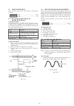
2-4-2. SYNC AGC Check (MA-286 Board)
Mode
E-E
Signal
Color bar
Measurement point
IC201 pin
#•
Measuring instrument
Oscilloscope
Specified value
A=2.10 ± 0.14Vp-p
[Check Method]
1)
Check that the Video signal level (A) satisfies the specified
value.
Fig. 7-2-5.
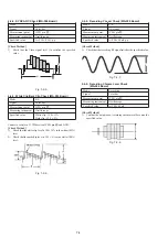
2-4-3. White Clip/Dark Clip Check (MA-286 Board)
Mode
E-E
Signal
Color bar
Measurement point
IC201 pin
#
Measuring instrument
Oscilloscope
Specified value
White clip : 190 ± 15%
Dark clip : 52.5 ± 5%
Connect a resistor of 3.3
Ω
between IC201 pin
$™
and GND.
[Check Method]
1)
Check that the white clip level is 190 ± 15% to the white (100%)
level.
2)
Check that the dark chip level is 52.5 ± 5% to the white (100%)
level.
Fig. 7-2-6.
2-4-4. Recording Y Level Check (MA-286 Board)
Mode
E-E
Signal
No-signal
Measurement point
IC201 pin
!•
Measuring instrument
Oscilloscope
Specified value
A=250 ± 50mVp-p
[Check Method]
1)
Check that the recording RF signal satisfies the specified value.
Fig. 7-2-7.
2-4-5. Recording Chroma Level Check
(MA-286 Board)
Mode
Recording
Signal
Color bar
Measurement point
IC201 pin
!¢
Measuring instrument
Oscilloscope
Specified value
A=380 ± 40mV
[Check Method]
1)
Confirm the amplitude of recording chroma level becomes the
specified value.
Fig. 7-2-8.
A
A
H


