

6
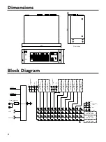
Rear panel
1
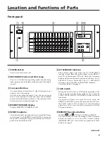
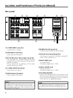
S-VIDEO INPUT Connectors
Accept S-video (Y/C) signals.
2
VIDEO INPUT Connectors
Accept composite video signals.
3
REF IN (Reference Video Input) Connectors
The video signals are switched by being synchronized
with the V-sync puls of the composite video-signal from
the REF IN connectors.
The two terminals are loop-through, and it has high-
impedance termination (47 k
Ω
).
4
S-VIDEO OUTPUT Connectors
Output S-video (Y/C) signals.
5
VIDEO Output Connectors
Output composite video signals.
6
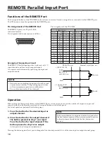
REMOTE Parallel Input Port
Use this port to control the PVS-1240S externally.
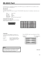
7
RS-232C Serial Input/Output Port
Use this port to control the PVS-1240S using the SRP-
C5000A system controller or a PC.
8
AUDIO INPUT Jacks
Accept audio signals.
The reference output level is –10 dBu.
9
AUDIO OUTPUT Jacks
Output audio signals.
The reference output level is –10 dBu.
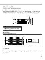
0
VOLTAGE SELECTOR
Set the VOLTAGE SELECTOR to the position of your
local power line voltage before connecting the AC power
cord to wall outlet. If the plug of AC power cord does not
fit the outlet, use the supplied plug adaptor.
IN
THRU OUT
REMOTE
PARALLEL IN 2
RS-232C
VOLTAGE SELECTOR
120V
230V
PARALLEL IN 1
IN1-18 / OUT1-4
IN9-12
S VIDEO
REF IN
VIDEO
AUDIO
INPUT
OUTPUT
VIDEO
AUDIO
1
2
3
4
1
2
3
4
5
6
7
8
9
10
11
12
1
2
3
4
5
6
7
8
9
10
11
12
1
2
3
4
1
2
3
4
L
R
S VIDEO
1
2
3
4
L
R
L
R
NOTE
Although the video and S-video systems are switched
simultaneously, a video input signal cannot be output via
S-video output. Likewise, an S-video input signal cannot
be output via video output.
Location and Functions of Parts (continued)
NOTE
The supplied plug adaptor and a plug attached to the
power cord, are not available in UK, Hong Kong, and so
on.
Summary of Contents for PVS-1240S
Page 14: ...14 ...