background image

Chapter 11

Setup Menus

11-8

Chapter 11

Setup Menus

11-4  Items in the Extended Setup Menu

Menu items in the range 100 to 199, relating to the control panels

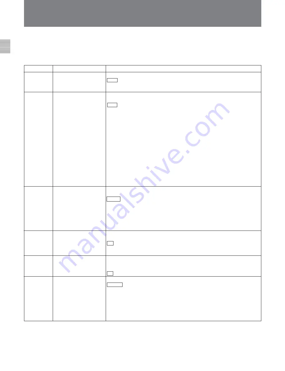
The extended setup menu contains the following
items.

11-4  Items in the Extended Setup Menu

Item number

Item name

Settings

101

SELECTION FOR
SEARCH DIAL ENABLE

Select how the unit enters the search mode.

DIAL :

 Turning the search dial switches to search mode.

KEY:

 One of the JOG, SHUTTLE, and VAR buttons must be pressed to switch to

search mode.

102

MAXIMUM SPEED

Select the fast forward and rewind tape speed and also search mode speed
during tape playback.

MAX :

 Perform fast forward, rewind, and search mode playback at the maximum

speeds.

MX/24:

 Perform fast forward and rewind at the maximum speeds, and search

mode playback at up to 24 times normal speed.

×

24:

 Perform fast forward and rewind at 24 times normal speed, and search

mode playback at up to 24 times normal speed.

Maximum fast forward and rewind speeds

• Analog cassette: 35 times (525-line mode) or 42 times (625-line mode) normal

speed

• Betacam SX/MPEG IMX cassettes: 60 times normal speed (525-line mode) or

78 times (625-line mode)

Maximum search mode speeds

• Analog cassette: 35 times (525-line mode) or 42 times (625-line mode) normal

speed

• Digital Betacam cassette: 50 times normal speed

104

AUDIO MUTING TIME

Select the length of time for which audio muting occurs when the unit switches to
playback either from stopped or from still playback in the search mode.

off :

 Set the audio muting time to zero (i.e. no muting).

0.1S ... 1.0S:

 Set the audio muting time from 0.1 second to 1.0 second, in 0.1-

second increments.

105

REFERENCE SYSTEM
ALARM

Select whether or not to display a warning when the video reference signal is not
supplied.

off: 

No warning.

on :

 Flash the STOP button as a warning.

103

AUDIO SELECTED LINE
OUT

Select the output signal to the MONITOR OUTPUT connectors during playback of
analog Betacam-format tape.

MANU :

 Output the signals selected by the audio signal selection buttons on the

lower control panel.

AUTO1:

 Output stereo, using the AFM channels (3 and 4) for playback from

metal tape, and the LNG channels (1 and 2) for playback from oxide tape.

AUTO2:

 Output the signals selected by the audio signal selection buttons on the

lower control panel, but during variable speed playback, if AFM is selected,
automatically switch to LNG.

106

Select the capstan servo lock mode.

PANEL :

 The capstan servo lock mode is determined by the function menu item

CAPSTN.

2F:

 The capstan servo locks every two fields regardless of the setting of the

function menu item CAPSTN.

4F:

 The capstan servo locks every four fields regardless of the setting of the

function menu item CAPSTN.

8F (For 625-line mode only):

 The capstan servo locks every eight fields

regardless of the setting of the function menu item CAPSTN.

(Continued)

CAPSTAN LOCK

In the “Settings” column of the table, the factory
default settings are indicated by an enclosing box.

Summary of Contents for MSW-M2100

Page 1: ...DIGITAL VIDEOCASSETTE PLAYER MSW M2100 MSW M2100P MSW M2100E MSW M2100EP OPERATION MANUAL English 1st Edition Revised 5 ...

Page 2: ...he UL LISTED power cord specified below DO NOT USE ANY OTHER POWER CORD Plug Cap Parallel blade with ground pin NEMA 5 15P Configuration Cord Type SJT three 16 or 18 AWG wires Length Miminum 1 5 m 4 ft 11 in Less than 2 5 m 8 ft 3 in Rating Minimum 10 A 125 V Using this unit at a voltage other than 120V may require the use of a different line cord or attachment plug or both To reduce the risk of f...

Page 3: ...3 6 Using a Memory Stick 3 11 3 6 1 Notes on Memory Stick 3 11 Chapter 4 Playback and File Transfer 4 1 Preparations for Playback 4 1 4 1 1 Switch and Menu Settings 4 1 4 1 2 Time Data Selection 4 2 4 1 3 Playback With SDTI CP Output 4 2 4 2 Playback Procedures 4 3 4 2 1 Normal Playback 4 3 4 2 2 Playback in Jog Mode 4 3 4 2 3 Playback in Shuttle Mode 4 4 4 2 4 Playback in Variable Speed Mode 4 4 ...

Page 4: ...w of Auto Event Detector Functions 9 1 9 2 Event Output and Recording 9 1 Chapter 10 Function Menu 10 1 Overview 10 1 10 1 1 Function Menu Configuration 10 1 10 1 2 Using the Function Menu 10 2 10 2 Function Menu Item List 10 3 Chapter 11 Setup Menus 11 1 Setup Menu Configuration 11 1 11 2 Setup Menu Operations 11 2 11 3 Items in the Basic Setup Menu 11 5 11 4 Items in the Extended Setup Menu 11 8...

Page 5: ...ormance heads and compatibility playback function The newly developed high performance heads and dynamic tracking DT technology provide high density playback in narrow tracks with high reliability In addition to the MPEG IMX playback heads this unit is also equipped with Betacam SX format playback heads and analog Betacam DT heads to provide compatibility playback functions and allowing a wide var...

Page 6: ...for multichannel applications but also for high quality audio editing Playback of SDTI compressed data This unit is fitted with SDTI CP output complying with SMPTE 326M and can therefore be used for transferring MPEG 2 data audio data metadata and so on to a VTR or nonlinear device Newly developed multifunction control panel While a compact 4U size this unit has a front panel which provides a wide...

Page 7: ...he necessary editing functions are provided to set and amend edit points to preview and review results of editing and so on DMC playback This allows automatic playback with a varying speed memorized beforehand for the desired segment Tele File functions Tele File enables data writing reading between cassettes with memory labels and VTRs It increases the efficiency of operations such as cuing up an...

Page 8: ...les of use 1 2 Example System Configuration Digital analog cassette BVE series editor Tape control Analog composite Audio monitor Analog composite component MSW M2100 M2100P Video monitor VTR with SDTI SDI connectors or analog VTR Audio video server system SDTI CP SDI SDI Analog audio Basic System ...

Page 9: ...met e VTR Manager may not operate properly CPU 1 GHz or higher Memory 256 MB or greater OS Windows XP 2000 DirectX 8 1b or higher Language English Available hard disk space 5 MB or more Monitor resolution XGA 1024 768 or more recommended Microsoft and Windows are registered trademarks of Microsoft Corporation in the United States and or other countries To install the software 1 Insert the CD ROM i...

Page 10: ...censing may be obtained from MPEG LA LLC See http www mpegla com 1 3 MPEG 4 Visual Patent Portfolio License 1 4 MPEG 2 Video Patent Portfolio License ANY USE OF THIS PRODUCT OTHER THAN CONSUMER PERSONAL USE IN ANY MANNER THAT COMPLIES WITH THE MPEG 2 STANDARD FOR ENCODING VIDEO INFORMATION FOR PACKAGED MEDIA IS EXPRESSLY PROHIBITED WITHOUT A LICENSE UNDER APPLICABLE PATENTS IN THE MPEG 2 PATENT PO...

Page 11: ... 2 Location and Function of Parts Z CTL TC TC MENU ON OFF KEY INHI FRONT REAR PANEL SEL CONTROL PANEL REMOTE NEWORK 1 9P 2 50P RS 232C Lower control panel unlock buttons Pushing in these buttons allows you to open the lower control panel Upper control panel see page 2 2 Lower control panel see page 2 4 Switch panel access by opening the lower control panel see page 2 13 MSW M2100E M2100EP MSW M210...

Page 12: ...WORK indicator flashes during data connection MXF file transmission For details on the network functions using the NETWORK button refer to the Operation Manual of the BKMW E3000 Network Interface Board 3 REMOTE buttons Press one of these buttons to select the device controlling this unit 1 9P This unit is controlled by the device connected to the REMOTE 1 IN 9P or REMOTE 1 OUT 9P connector The but...

Page 13: ...t The BETACAM SP indicator lights when the format is Betacam or Betacam SP 7 PHONES jack and control Connect stereo headphones with an impedance of 8 ohms to monitor the sound during playback The control knob adjusts the volume It is possible to set an internal board switch so that the output volume from the MONITOR OUTPUT L and R connectors is controlled simultaneously For details refer to the In...

Page 14: ...ge 2 6 3 Menu control buttons see page 2 6 4 Time data menu display section see page 2 7 5 MULTI CONTROL knob and SHIFT indicator see page 2 8 6 RESET button see page 2 8 7 Search control section see page 2 8 9 Tape transport control section see page 2 10 q ALARM indicator and KEY INHI indicator see page 2 11 qa DMC playback control section see page 2 11 qs Shot mark section see page 2 12 8 GOOD S...

Page 15: ...nt indicating the reference level lights In this mode only the segment of the display corresponding to the current audio level lights If the audio level exceeds the maximum display level the top segment flashes and if the audio level goes below the minimum display level the bottom segment flashes 2 Audio setting display section OVER indicator While the unit is in playback mode this lights when the...

Page 16: ...LL CH channels indicator This indicator lights when adjustment of all audio channels by the rightmost PB control CH8 ALL CH is selected 2 CHANNEL CONDITION indicator A three color indicator shows the state of the playback signal Green The state of the playback signal is good Yellow The playback signal is somewhat deteriorated but playback is possible Red The playback signal is deteriorated When th...

Page 17: ...at indicator This indicator shows the current playback format DB Digital BETACAM format IMX MPEG IMX format bit rate 50 Mbps 8 audio channels IMX4 MPEG IMX format bit rate 50 Mbps 4 audio channels SX Betacam SX format SP Betacam SP format No display Betacam format System frequency indicator Displays the current playback field frequency and the bit rate of recording or SDTI CP output 525 625 indica...

Page 18: ...lue of the setting changes by a greater amount when you rotate the knob 6 RESET button To reset the CTL value displayed in time data display area 1 press this button Resetting the CTL value erases all edit points 7 Search control section 1 SHUTTLE button To use the search dial for playback in shuttle mode press this button turning it on For details of playback in shuttle mode see the description o...

Page 19: ... SHUTTLE JOG and VAR buttons to select shuttle jog variable speed modes Playback mode Operations and functions Shuttle Press the SHUTTLE button or the search dial so that the SHUTTLE button lights then turn the search dial Playback is carried out at a speed determined by the position of the search dial The playback speed range is as follows Using a Digital Betacam tape 50 times normal speed Using ...

Page 20: ...ss the STANDBY button turning it off If 8 minutes value can be varied using setup menu item 501 elapse in standby mode the unit automatically switches out of standby mode to protect the tape 3 STOP button To stop playback press this button turning it on When you stop playback the unit switches to still playback On the MSW M2100E M2100EP press and light the button to stop file transmission to the n...

Page 21: ...LAY IN or PLAY OUT button which is lit indicating an existing DMC playback control point to delete the corresponding DMC playback control point The button either goes off or flashes When the button flashes it is necessary to set the deleted DMC playback control point again To cancel the DMC mode hold down the DMC FEED button and press the DELETE button 4 TRIM buttons Use these buttons to trim a DM...

Page 22: ...this button cues up the tape to the on air start point The button then starts flashing to indicate that the unit is ready for DMC playback operation To start DMC playback press the button again 7 LEARN button After setting a speed variation start point STUNT IN point and a speed variation end point STUNT OUT point pressing this button makes the tape start running You can then use the search dial t...

Page 23: ...imilar control panel to this unit When two control panels are connected to the unit the PANEL SELECT switch is used to specify which panel be enabled to control the unit FRONT Enables the control panel connected to the CONTROL PANEL connector on the switch panel REAR Enables the control panel connected to the CONTROL PANEL connector on the connector panel When setup menu item 117 is set to PARA th...

Page 24: ...t section 1 AUDIO OUTPUT CH1 to CH4 channels 1 to 4 connectors XLR 3 pin male These connectors output analog audio signals for channels 1 to 4 2 CUE OUT cue audio output connector XLR 3 pin male When playing back a digital Betacam tape this connector outputs the cue audio signal 2 Analog video input output section AUDIO OUTPUT CUE CH1 OUT CH2 CH3 CH4 1 AUDIO OUTPUT CH1 to CH4 connectors 2 CUE OUT ...

Page 25: ...These connectors output up to four sets 8 channels channels 1 2 3 4 5 6 and 7 8 of AES EBU format digital audio signals 4 Network connection section MSW M2100E M2100EP only Ethenet connector Connect to a network by 10 100 1000Base T CAUTION For safety do not connect the connector for peripheral device wiring that might have excessive voltage to this port Follow the instructions for this port 5 Dig...

Page 26: ...pin Not used 5 REMOTE 1 IN 9P connector D sub 9 pin When using this unit together with an MSW 2000 series VTR recorder or a D 1 D 2 or Betacam VTR and a BVE series BVE 900 910 2000 9000 9000P 9100 9100P or other editor connect the optional 9 pin remote control cable from the other unit to this connector Depending on the setting of setup menu item 211 you can use this connector alone or in a loop t...

Page 27: ...This outputs the audio signals whose output destination was set to R with the audio signal selection buttons in the audio control section If multiple tracks have been set to R the signals of those tracks are mixed for output 2 MONITOR OUTPUT L connector XLR 3 pin male This outputs the audio signals whose output destination was set to L with the audio signal selection buttons in the audio control s...

Page 28: ...OTE 1 OUT 9P SDI OUTPUT SDI OUTPUT 3 SUPER SDI INPUT REF VIDEO INPUT REF VIDEO INPUT 3 1 Connections to External Devices Chapter 3 Preparations 3 1 1 Connections to Digital Devices BVM 1454 series video monitor 75 Ω termination switch OFF MSW A2000 A2000P M2000 M2000P recorder MSW M2100 M2100P M2100E M2100EP a player 75Ω termination switch ON Reference signal a The figure shows the MSW M2100 M2100...

Page 29: ...T CH1 to CH4 VIDEO INPUT COMPOSITE VIDEO INPUT COMPONENT REMOTE 9P COMPOSITE VIDEO OUTPUT COMPONENT VIDEO OUTPUT COMPOSITE VIDEO OUTPUT REMOTE 9P AUDIO OUTPUT CH1 to CH4 REMOTE 1 IN 9P 3 1 2 Connections to Analog Devices Video monitor DVR 28 28P 20 20P D2 VTR BVH 3000 3000PS 1 inch VTR etc recorder BVW 75 70 65 60 series Betacam SP VTR recorder MSW M2100 M2100P M2100E M2100EP a a The figure shows ...

Page 30: ...ith devices that support the SDTI CP interface for dubbing video and audio signals SDI OUTPUT 3 SDTI CP OUTPUT SDTI CP INPUT REF VIDEO INPUT Reference signal 75Ω termination switch ON MSW M2100 M2100P M2100E M2100EPa VIdeo monitor VIdeo monitor Data storage unit for nonlinear editing system MAV 555 etc a The figure shows the MSW M2100 M2100P ...

Page 31: ...can be connected to a 10 100 1000Base T network You can send video audio and metadata as MXF files by operating the control panel of the VTR or using a control computer connected via the network A network connection example for the MSW M2100E M2100EP is shown below MSW M2000E M2000EP MSW M2100E M2100EP Router Hub Audio video server Server room 3 1 Connections to External Devices Ethernet 10 100 10...

Page 32: ...t a reference video signal as shown below Reference signal for video output and servo system The output from the internal reference video signal generator is supplied to the output video signal and servo circuits as a reference signal External sync signal for the internal reference video signal generator The internal reference video signal generator is synchronized to an input reference video sign...

Page 33: ...diting operations Items relating to preroll Items relating to tape protection Items relating to the time code generator Items relating to video control Items relating to audio control Items relating to digital processing For detailed information about the items except for the basic setup menu items relating to the hours meter of these menus and how to use them see Chapter 11 Setup Menus For detail...

Page 34: ...ee Section 11 3 Items in the Basic Setup Menu page 11 5 Information displayed Note The display shown above corresponds to the factory default settings of the unit Changing the setting of setup menu item 005 allows different time data to be displayed in the lower line of the display For details see Section 11 3 Items in the Basic Setup Menu page 11 5 Display Meaning CTL CTL counter data TCR LTC rea...

Page 35: ...assette is not loaded STANDBY OFF Standby off mode T RELEASE Tape tension released STOP Stop mode F FWD Fast forward mode REW Rewind mode PREROLL Preroll mode PLAY Playback mode servo unlocked PLAY Playback mode servo locked LOCK PLAY Variation from normal speed Capstan override mode see page 4 5 JOG STILL A still picture in jog mode JOG FWD Jog mode in forward direction JOG REV Jog mode in revers...

Page 36: ...assette is drawn into the unit and the STANDBY and STOP buttons light If message ERR 10 appears in the time data menu display section there is moisture condensation in the unit Removing slack from the tape Press in one of the reels with a finger and turn gently in the direction shown by the arrows until there is no slack in the tape Ejecting a cassette Press the EJECT button Note Ejecting is a loc...

Page 37: ...e Press in the red record inhibit plug ON Return this plug to its original position to enable recording on the tape again OFF 3 5 3 Preventing Accidental Recording of Shot Marks To prevent shot marks from being accidentally recorded on a tape press in the red record inhibit plug on the cassette ...

Page 38: ... unit does not support Memory Stick PRO products with more than 2 gigabytes of capacity Note on data read write speed Data read write speed may vary depending on the combination of the Memory Stick and Memory Stick compliant product you use Before using a Memory Stick You cannot record or erase data when the write protect tab on the Memory Stick is set to LOCK We recommend backing up important dat...

Page 39: ...ory Stick do not shake the camera or subject it to shock Do not turn off the power of the camera or remove the Memory Stick This may damage the data For details refer to the Maintenance Manual Memory Stick and are the trademarks of Sony Corporation Memory Stick Duo and are trademarks of Sony Corporation Memory Stick PRO and are trademarks of Sony Corporation 3 6 Using a Memory Stick ...

Page 40: ...ils on each setting see the pages indicated in parenthesis Z CTL TC TC MENU Audio signal selection buttons see page 2 6 Select the audio channel s to be monitored POWER switch side ON TCR setting see page 10 3 Select the time code to be displayed REMOTE buttons see page 2 2 off PB controls see page 2 6 Adjust the audio playback levels CTL TC setting see page 10 3 Select the time data to be display...

Page 41: ...on menu page 1 as follows Output time code The setting of setup menu item 606 determines whether the time code output from the TIME CODE OUT connector is the time code generated by the internal time code generator REGEN or the playback time code TAPE 4 1 3 Playback With SDTI CP Output Irrespective of tape format video and audio signals can be played back only at normal playback speed TCR setting D...

Page 42: ...he SERVO indicator lights To stop playback Press the STOP button 4 2 Playback Procedures If you play back to the end of the tape The tape is automatically rewound and stops It is possible to disable the automatic rewind function by changing the setting of setup menu item 125 When using the Dolby noise reduction system When using an analog Betacam cassette you can use Dolby C noise reduction for au...

Page 43: ... starts 3 To stop playback in shuttle mode return the search dial to the center position or press the STOP button The function to toggle between jog mode and shuttle mode each time the search dial is pressed can be disabled by changing the setting of setup menu item 101 To return to normal speed playback Press the PLAY button To alternate between normal speed playback and shuttle mode playback Set...

Page 44: ...k the same program Two types of playback operation are available using the capstan override function capstan override playback To perform temporal capstan override playback 1 A Hold down the PLAY button and turn the search dial in the desired direction to adjust the playback speed The range of speed adjustment is 15 in steps of 1 B Hold down the PLAY button and press the TRIM buttons to adjust the...

Page 45: ...to feed playback Auto feed playback is a function for feed mode playback of the segment between a specified IN point and OUT point By connecting this unit to a recorder VTR with a RECEIVE STANDBY function MAV 555 2000 etc via the SDTI CONTROL PANEL interface and executing auto feed playback on this unit you can record the interval between the IN and OUT points on the recorder 1 On the HOME page of...

Page 46: ...yback immediately after preroll Normal speed playback DMC playback Normal speed playback Press the LEARN button Z 2 5 1 4 7 3 3 4 6 4 3 1 Overview DMC playback allows you to vary the playback speed for a certain section of a tape in variable speed mode from 1 to 3 times normal speed for digital Betacam playback from 1 to 3 times normal speed for MPEG IMX playback from 1 to 2 times normal speed for...

Page 47: ...ashing the speed variations are stored in memory On passing the speed variation end point the MEMORY indicator changes frobÎfilashing to continuously lit and the variable speed storing ends 7 Press the STOP button to stop the tape If the MEMORY indicator lights continuously before the speed variation end point This indicates that the memory became full at that point It is therefore not possible to...

Page 48: ...ed speed and then playback continues at normal speed and the tape stops at the on air end point To start playback immediately after preroll Press the LEARN button The LEARN button lights and after preroll DMC playback is carried out for the section from the speed variation start point then playback continues at normal speed from the speed variation end point To stop the tape during DMC playback Pr...

Page 49: ...TC TC MENU REMOTE NEWORK 1 9P 2 50P RS 232C 4 4 1 Preparation for File Transmission Switch and menu settings Before beginning transmission make necessary switch and menu settings Power switch side ON NETWORK button page 2 2 lit For details on each setting refer to the manual or see the page indicated in parenthesis MSW M2100E M2100EP Destination server setting BKMW E3000 Operation Manual Setup men...

Page 50: ...d down the ENTRY button and press the PLAY button File transfer starts When sending to an FTP server You can send a portion between the IN and OUT points you registered as a file by pressing the PLAY button while holding the ENTRY button down Z 3 4 1 2 When sending to an HTTP server You can send the data from the registered IN point or cued point for the duration specified using the setup menu ite...

Page 51: ...r etc Writing on this unit Modifying and erasing on this unit Recording start mark Automatically written at the start of recording Possible erasure only Shot mark 1 and shot mark 2 Written by a manual shot mark operation during recording or editing Post mark Not written Written only on this unit Written by a button operation during playback while stopped or during a search Shot marks are indicatio...

Page 52: ...RKER Details of the shot mark operation menu The shot mark operation menu comprises two items G01 and G02 The detailed contents appear in the following table Changing the menu settings The basic procedure for accessing menu items and changing settings is the same as for the setup menus Note however the operations in To change the settings of menu items with sub items page 11 3 for item G02 Similar...

Page 53: ...ttons To stop reading Press the STOP button Reading shot marks from more than one cassette After changing the cassettes carry out the reading operation again Data written in the new cassette will be added as long as the total does not exceed 200 shot marks For example if 190 shot marks have already read in only 10 shot marks will be read from the new tape In the shot mark list see page 5 4 the dat...

Page 54: ...ECT DELETE SHT MRK Example of list display The following figure shows how the list is organized Selecting a shot mark Turn the MULTI CONTROL knob to align the asterisk cursor with the desired shot mark Entering virtual shot marks When the REC ERASE indicator is off hold down the ENTRY button and press the MARK button Z ENTRY button LIST button Shot mark number of current cursor position total numb...

Page 55: ...follows EXIT PREV NEXT OFF ON SHT MRK 2 Press the F1 PREV or F2 NEXT button to select a shot mark type 3 Press the F4 ON or F3 OFF button to switch between ON displayed and OFF not displayed 4 To return to the shot mark list press the F6 EXIT button Deleting a shot mark from the list To delete a shot mark or the shot mark list you can use the F2 SELECT button instead of the MARK button and the F3 ...

Page 56: ...to turn off the REC ERASE indicator 5 3 4 Cuing Up to Shot Marks Cuing up to a selected shot mark Use the following procedure 1 Select the desired shot mark from the shot mark list 2 Press the PREROLL button Cuing up to shot marks adjacent to the current tape position index function 1 In item G01 of the shot mark operation menu page 5 2 select one of recording start mark shot mark 1 shot mark 2 an...

Page 57: ...shot data on the shot mark list Turn the MULTI CONTROL knob to position the cursor on a separator in the shot mark list If there is shot data recorded when the immediately following shot mark was written it appears in the display as shown below You can sort the shot marks in the list based on the shot data For details see the next section First shot mark in the group NO TIME CODE 180 SHOT MARK 012...

Page 58: ...r example if shot marks have been read in twice from the same cassette these can be collated as shown in the following figure Before sorting 180 NO TIME CODE SHOT MARKER 012345 DNW_ 0123 4567 011 S1 10 04 05 11 012 V 10 07 05 02 017 R 10 05 35 24 013 R 10 08 35 04 014 S2 10 09 05 11 015 R 10 10 35 24 016 R 10 10 36 00 180 NO TIME CODE SHOT MARKER 012345 DNW_ 0123 4567 011 S1 10 04 05 11 016 V 10 0...

Page 59: ...of 0 5 mm the IC can be attached to cassettes as a memory label Memory capacity 1 KB user area rewritable Data transfer speed 100 kbps Security functions Reading and writing authorization can be controlled through multiple passwords and permission settings Data management in clip units In Tele File data is managed in units called clips A clip consists of the following data items whose settings can...

Page 60: ...and when the current function menu page is HOME HOME2 or page 1 to page 5 the Tele File menu opens automatically whenever a Tele File label is detected on a cassette loaded into the VTR For details about setup menu item 134 see Section 11 4 Items in the Extended Setup Menu page 11 11 Configuration of the Tele File menu The Tele File menu has a tree structure as illustrated below When the menu firs...

Page 61: ...Point WP Mark R TELE FILE TEST 01 00 00 02 10 ON KEEP 00 00 31 10 00 00 57 10 Monitor display Final data recording date Data type Clip data No 0001 Clip data No 0002 Clip data No 0003 Title Number of selected clip Remaining memory percentage a Tele File menu indicator Indicates that the menu display section is currently displaying the Tele File menu Data type indicator Indicates the type of data s...

Page 62: ...for the data selected in the clip The cursor changes from to Note In the following cases the SELECT item does not appear and it is not possible to select a data modification mode When setup menu item 133 is set to REMOTE When the memory label itself is write protected For more information about clip data modifications see Section 6 3 3 Modifying Clip Data page 6 7 F3 T Selects data in a clip With ...

Page 63: ...ecording start point IN Point IN point OUT Point OUT point Tk Take number Cut Cut number Scn Scene number Comment Comment Clip data No 0001 Data is displayed for 1 clip per line Clips are assigned continuous numbers beginning with No 0001 for the clip on the top line To select clips Rotate the MULTI CONTROL knob in clip data display mode The data for the selected clip appears in the menu display s...

Page 64: ... Using Clip Data In clip data display mode you can use clip data to preroll and cue up To preroll to the cue point IN point or OUT point 1 Select a clip 2 Select the cue point the IN point or the OUT point 3 Press the PREROLL button The unit exits from the Tele File menu and prerolls to the position of the selected data The preroll time is according to the setting of setup menu item 001 Note The u...

Page 65: ...essage appears Press one of the following buttons to confirm or cancel the operation F1 CANCEL Cancels the deletion and returns to clip data display mode F2 OK Executes the deletion and returns to clip data display mode F4 DEL LN Deletes the selected clip A confirmation message appears Press one of the following buttons to confirm or cancel the operation F1 CANCEL Cancels the deletion and returns ...

Page 66: ... set timecode data Proceed as follows to make or change settings for cue point IN point and OUT point data 1 Select a clip 2 Select cue point IN point or OUT point 3 Press the F2 SELECT button The unit enters clip data modification mode 4 Press the F2 MODIFY button The two most significant digits begin to flash and the data can be set or modified 5 Press the F3 T or F4 t button until the digit tha...

Page 67: ...dification mode 4 Press the F2 MODIFY button The data entry area begins to flash and the data can be set 5 Select the data by pressing the F3 or F4 button or rotating the MULTI CONTROL knob 6 Press the F2 SET button The data setting is confirmed and the unit returns to clip data display mode To make take number cut number and scene number settings Proceed as follows to make take number cut number ...

Page 68: ... after the place where you want to insert starts flashing and then press the F6 INSERT button 8 Press the F2 OK button The comment is confirmed and the unit returns to clip data display mode 6 3 4 Undo Resume Functions Undo function The undo function cancels all modifications and returns the data to the state it was in when first read Press the F5 UNDO button in clip data display mode A confirmati...

Page 69: ...igned to Tele File maximum 24 characters The ID can be modified Administrator data Data about the administrator of the cassette or tape material maximum 16 characters The administrator data can be modified Model name The model name of the VTR that recorded most recently to the tape Serial number The serial number of the VTR that recorded most recently to the tape Write inhibit setting Whether the ...

Page 70: ... setting is confirmed Note In the following cases the SELECT item does not appear and it is not possible to select a data modification mode When setup menu item 133 is set to REMOTE When the memory label itself is write protected 6 3 Tele File Menu To format the Tele File memory You can format the Tele File memory erase all modifiable data However the memory cannot be formatted in the following ca...

Page 71: ... contains information such as the device that recorded the material and whether the material is the original or a copy The Source Pack section contains information about when where who recorded the material A UMID with a Basic section only is called a Basic UMID A UMID with both Basic and Source Pack sections is called an Extended UMID The following figure shows a general overview of the informati...

Page 72: ...nected to the COMPOSITE VIDEO OUTPUT 3 SUPER connector or the SDI OUTPUT 3 SUPER connector on the connector panel displays all UMID items at once The display of each line is explained below 1 Instance Number generation method and Instance Number The generation method is displayed as follows CP 16 16 bit PRS pseudo random sequence Copy No method 24PRS 24 bit PRS method others Other than the above 2...

Page 73: ...shown for Target position data 2nd character Indicates higher than sea level indicates lower than sea level XXXXXXXm Altitude data unit meters Y The number of satellites used to calculate position data hexadecimal D DOP dilution of precision value between Y and D Displayed when a supportive apparatus was used A space blank is displayed when no supportive apparatus was used 6 Longitude Following W ...

Page 74: ...be output to SDI signals when playing back a tape Information such as shot marks recorded on the tape can also be converted into essence marks and output Selecting whether to output essence marks You can select whether or not to output essence marks when you play back a tape Make this selection using setup menu item 657 ESSENCE MARK TAPE OUTPUT See page 11 16 for more information about setup menu ...

Page 75: ...not to convert into essence marks and output events detected by the AED during playback normal playback variable speed playback and jog playback Make this selection using setup menu item 659 AED ESSENCE MARK CONVERT See page 11 16 for more information about setup menu item 659 Recording event marks in a Tele File label The time code of cut events detected by the AED can be written to a Tele File l...

Page 76: ...s as F4 CTL TC in function menu HOME page is set to TC CTL TC TC MENU HOME F1 F2 F3 F4 F5 F6 Settings values Menu items functions HOME2 page user defined function keys Up to six function keys can be defined i e six functions can be assigned to the F1 to F6 buttons in the HOME2 page You can select and define the following function keys Functions selected from the function menu items in the HOME pag...

Page 77: ...button selects the next page in the order HOMEt1t2t3t4t5tHOME The v button selects the next page in the order HOMEt5t4t3t2t1tHOME When there are setup menu definitions on page 6 page 6 is displayed between page 5 and the HOME page With one of menu pages 1 to 5 displayed pressing the HOME button changes the page to the HOME page Pressing the HOME button when the HOME or HOME2 page is displayed chan...

Page 78: ...played in Hours Minutes Seconds Frames format F5 MENU Puts the system into setup menu mode see Chapter 11 When the current setup menu settings are the same as the contents of any of menu banks 1 to 3 or the factory defaults the corresponding indication 1 2 3 or dflt appears 1 Same as menu bank 1 2 Same as menu bank 2 3 Same as menu bank 3 dflt Same as factory defaults The function menu has the fol...

Page 79: ...played setting flashing you can rotate the MULTI CONTROL knob to adjust the value for the chroma signal output level F4 HUE 525 line mode C PHAS 625 line mode Sets the color phase phase relative to burst PRESET Regardless of manually set values the color phase is set to the standard value Manual setting With the displayed setting flashing you can rotate the MULTI CONTROL knob to adjust the value a...

Page 80: ... output signal subcarrier phase Setting method With the displayed setting flashing you can rotate the MULTI CONTROL knob to adjust the output signal subcarrier phase across the range 200 ns relative to this unit s input reference signal Adjust this item when you are using composite signals in editing and want to adjust the output signal subcarrier phase precisely to match a reference signal Even w...

Page 81: ... fields For tape output color framing may not match the reference signal When playing back a tape that was recorded with composite source signals a vertical shift in the video H shift occurs When setup menu item 712 is set to ON 8F The capstan servo locks in units of 8 fields For tape output color framing matches the reference signal Even when playing back a tape that was recorded with composite s...

Page 82: ...s the Tele File menu For details of the Tele File menu see Section 6 3 Tele File Menu page 6 3 F2 UMID Displays UMID information during recording playback For details of UMID see Chapter 7 F5 SUPUTL Selects the type of MXF files to be sent For details of the operation see Section 4 4 2 File Transmission Using the Control Panel page 4 11 For details on types of MXF files refer to the BKMW E3000 Ope...

Page 83: ...isplay of the total number of hours the unit has been powered on and other information collected by the digital hours meter Settings relating to the preroll time superimposed text information switching between 525 line NTSC and 625 line PAL operation modes etc Settings relating to the menu banks for saving menu settings Item group Items 100 to 199 Items 200 to 249 Items 250 to 299 a Items 300 to 3...

Page 84: ...he monitor when the menu is customized when there are items which are not displayed However there is no indication in the menu display section that the menu has been customized For details about how to customize the setup menu refer to the Maintenance Manual Displaying a desired menu item When the menu item number displayed in the menu display is flashing you can change the menu item by turning th...

Page 85: ...ing value 3 When all required changes have been made press the F5 SET button This makes the new settings effective To abandon making changes and exit from the setup menu display Press the F6 EXIT button To change the settings of menu items with sub items When a selected menu item has sub items select a desired sub item using the procedure described in the section To display a desired sub item on t...

Page 86: ...ou can now change the selection between 525 line and 625 line operation modes 2 Switch the setting then press the F5 SET button 3 Turn the unit off Next time the unit is turned on it operates in the new mode Menu bank operations menu items B01 to B13 This unit allows menu settings to be saved in what are termed menu banks Saved sets of menu settings can be recalled for use as required To save the ...

Page 87: ...Determines whether to display the CTL count in 12 hour mode or 24 hour mode 12H 12 hour mode 24H 24 hour mode 005 DISPLAY INFORMATION SELECT Determines the kind of character information to be output from the COMPOSITE VIDEO OUTPUT 3 SUPER connector and the SDI OUTPUT 3 SUPER connector when the function menu item F4 CHARA is set to ON T STA Time data display information and the unit s status T UB T...

Page 88: ... played back in the simple playback mode 012 a CONDITION DISPLAY VIDEO MONITOR Specifies whether to add a channel condition indication to superimposed text when x1 is selected in menu item 011 disable Do not display ena1 Display an indication of both channel condition and tape time remaining time etc ena2 Display an indication of channel condition only ena3 Display an indication of tape time remai...

Page 89: ... current menu settings to the factory defaults Set it to bank 4 to use the contents of menu bank 4 as the current menu settings For details about menu bank 4 refer to the Maintenance Manual Item number Item name Settings Item number Item name Settings 037 LAST ERROR LOG NUMBER DISPLAY Specify whether the number of errors should be displayed as part of superimposed text information The number of er...

Page 90: ...ing occurs when the unit switches to playback either from stopped or from still playback in the search mode off Set the audio muting time to zero i e no muting 0 1S 1 0S Set the audio muting time from 0 1 second to 1 0 second in 0 1 second increments 105 REFERENCE SYSTEM ALARM Select whether or not to display a warning when the video reference signal is not supplied off No warning on Flash the STO...

Page 91: ...a over the range 3 to 3 Characterized by a zone around 1 and 1 where the tape speed is independent of the search dial rotation rate TYPE3 Tape speed varies linearly over the range 3 to 3 as shown in the figure belowb TYPE4 Tape speed varies stepwise as shown in the figure belowc over the range 2 to 2 Characterized by a zone around 1 and 1 where the tape speed is independent of the search dial rota...

Page 92: ...s 1 to 2 times normal speed on For MPEG IMX Betacam SX Digital Betacam tapes and analog tapes from 0 to 1 times normal speed 120 CTL LOCK IN VAR SHTL Select whether the tape transport should be phase locked to the CTL signal during playback in variable speed or shuttle mode off Not phase locked on Phase locked at the following speeds 1 0 5 0 5 1 0 and 2 0 times normal Item number Item name Setting...

Page 93: ...her or not to use synchronized operation for two or more VTRs DIS No synchronized operation ENA Use synchronized operation Note To use synchronized operation for two or more VTRs set item 201 to ENA on all of the VTRs Item number Item name Settings 135 TELE FILE THREAD COUNTER CLEAR MODE Selects whether to clear the thread counter when formatting a Tele File NOT CLEAR Do not clear the thread count...

Page 94: ...indow 254 MXF D10 DEST Select the registration number of the destination server for MXF D10 transmission using the control panel 1 to 5 Registration number of the server you registered in the Web window 252 NET REGEN Select whether to set file reception record when a recorder is used of a cassette with a Tele File memory label to NET REGEN mode to lock the time codes in recording to those of the t...

Page 95: ...oint NEG E When inconsistent DMC playback control points are set such as when a speed variation end point is before a speed variation start point or an on air end point is before an on air start point or when too many DMC playback control points are specified the previously set DMC playback control point is deleted NEG When inconsistent DMC playback control points are set such as when a speed vari...

Page 96: ...As the tape approaches the cue up point and the tape speed drops the tape transport switches to the pinch ON state a To give priority to editing accuracy select CAP Item number Item name Settings 501 STILL TIMER Select the time delay from the tape transport stopping either the stop mode or the still playback mode in search mode until the unit automatically switches to the tape protection mode in o...

Page 97: ...it enters Standby OFF mode and drum rotation stops 1M to 30M 1H to 4H to 8H Set the value in the range 1 minute to 8 hours Item number Item name Settings 606 TC OUTPUT SIGNAL IN REGEN MODE Select the signal output from the TIME CODE OUT connector during playback at normal 1 speed TAPE The playback time code signal is output without regeneration The time code values do not correspond to the video o...

Page 98: ...ayback off Do not output SHOTM Output Depending on the type of the detected shot marks the output essence marks are _RecStart _ShotMark1 or _ShotMark2 Notes Of the shot marks post marks are not converted to essence marks Shot mark detection timing depends on playback conditions 659 AED ESSENCE MARK CONVERT Select whether or not to convert into essence marks and output events detected during playba...

Page 99: ...Specify blanking for lines 12 to 19 BLANK Carry out blanking THROU Switch off blanking In 625 line mode 23 LINE 23 Specify blanking for line 23 HALF Carry out half blanking THROU Switch off blanking 9 22 LINE 9 LINE 22 Specify blanking for lines 9 to 22 BLANK Carry out blanking THROU Switch off blanking EDGE SUBCARRIER REDUCER MODE 20 LINE 20 Specify blanking for lines 20 BLANK Carry out blanking ...

Page 100: ...master the setup amount specified for this sub item is removed from the Betacam playback signal and is added to the output signal 0 0 7 5 10 0 Setting in this range in 0 5 increments 3 BETACAM PB LEVEL MSTER Set the Betacam playback signal to the master setting 0 0 7 5 10 0 Set the setup amount to be removed from the Betacam playback signal in this range in 0 5 increments 4 OUTPUT LEVEL MSTER Set ...

Page 101: ...IDE is selected the horizontal blanking width complies with RS170A and normally the blanking is widened and the image becomes narrower It is recommended to select NAROW at the editing stage then later for broadcast transmission to select WIDE to output a signal conforming to the standard Note however that NAROW has to be always selected for SDI signals 728 OUTPUT SCH PHASE Set the subcarrier H pha...

Page 102: ...ssigned to audio output channels 1 and 2 tr5 6 Tracks 5 and 6 assigned to audio output channels 1 and 2 tr7 8 Tracks 7 and 8 assigned to audio output channels 1 and 2 2 CH3 CH4 tr1 2 Tracks 1 and 2 assigned to audio output channels 3 and 4 tr3 4 Tracks 3 and 4 assigned to audio output channels 3 and 4 tr5 6 Tracks 5 and 6 assigned to audio output channels 3 and 4 tr7 8 Tracks 7 and 8 assigned to a...

Page 103: ... menu item Note Check to be sure that the selected tracks are being output from the SDI OUTPUT connectors Sub item 1 CH1 CH2 tr1 2 Assign tracks 1 2 to output channels 1 2 tr3 4 Assign tracks 3 4 to output channels 1 2 tr5 6 Assign tracks 5 6 to output channels 1 2 tr7 8 Assign tracks 7 8 to output channels 1 2 2 CH3 CH4 tr1 2 Assign tracks 1 2 to output channels 3 4 tr3 4 Assign tracks 3 4 to out...

Page 104: ...ETE button and press the TRIM button again To end the freeze Hold the DELETE button and press the TRIM button 905a AUTO FREEZE CONTROL Set the auto freeze function operation conditions for ending a freeze etc In normal playback if there is a sudden worsening of the channel condition entry into unrecorded area this function freezes the image DIS Disable the auto freeze function MODE1 End the freeze...

Page 105: ...play the setup utility menu on a monitor Connect a monitor to the COMPOSITE VIDEO OUTPUT 3 SUPER or SDI OUTPUT 3 SUPER connector of this unit SETUP MENU UTILITY F1 SETUP MENU DOWNLOAD F2 SETUP MENU UPLOAD F3 FORMAT STICK MEMORY STICK 12 1 1 Using Memory Stick Data Refer to the Maintenance manual Volume 1 for more information about downloading uploading and formatting operations To download files s...

Page 106: ...nob to switch EXEC OFF to EXEC ON SUP UTL EXIT SET UPLOAD SETUP EXEC ON HOME F1 F2 F3 F4 F5 F6 When you want to redo a file selection rotate the MULTI CONTROL knob to display the file name again then go back to step 2 The monitor screen display changes as follows ROM TO STICK File EXECUTE ON XXXXXXXX XXX SETUP MENU UPLOAD STICK VTR 5 Press the F5 SET button The selected file is uploaded Note Do no...

Page 107: ...ctions 12 3 3 Press the F5 SET button Formatting is executed If you are using a new Memory Stick or if an error occurs during execution of F3 FORMAT STICK use the sub mode to format the Memory Stick Note All data in the Memory Stick is erased when you execute F3 FORMAT STICK ...

Page 108: ...leaning cassette If you insert the cleaning cassette it is automatically ejected after a head cleaning operation which lasts for 5 seconds Follow the instructions with the cleaning cassette carefully as inappropriate use of the cleaning cassette can damage the heads For details refer to Section 1 17 in the Installation Manual 13 2 Head Cleaning Notes When carrying out head cleaning without using t...

Page 109: ...e the MSW M2100 M2100P Indications on the monitor The error message and code also appear superimposed on a monitor connected to the COMPOSITE VIDEO OUTPUT 3 SUPER connector or SDI OUTPUT 3 SUPER connector Depending on the error code an indication of the source of the problem may appear as a secondary error message ERROR 01 REEL TROUBLE 1 Error message displays To display error messages and codes s...

Page 110: ...vement of the reel table corresponding to the cassette size has been detected 22 REEL POS SENSOR The L cassette and S cassette positions of the reel table have been detected simultaneously 23 THRED RING SENS The thread end and unthread end states of the threading ring have been detected simultaneously 92 INTERNAL I F1 Abnormality in the interface between SYS CPU on SS 89 board and other CPU MPU ha...

Page 111: ...densation occurs ERR 10 appears in time data display area 1 If this happens the drum and capstan motors stop and the cassette is automatically ejected Then the durm starts to rotate again to dry its surface In this state the unit is not operable When the moisture has evaporated the error message disappears and the ALARM indicator goes off If ERR 10 appears and the ALARM indicator lights immediatel...

Page 112: ...till mode in units of 1 hour H04 THREADING mode Displays the total number of times tape has been threaded in the unit H12 DRUM RUNNING mode resettable Same as H02 except that the count is resettable This can be used as a guide in determining when to replace the drum H13 TAPE RUNNING mode resettable Same as H03 except that the count is resettable This can be used as a guide in determining when to r...

Page 113: ... supply Replace after 40 000 hours C C C C C R R R R R R R Replace at interval of 4000 hours R 13 5 Regular Checks 13 5 2 Maintenance Timings Use the following table as a timing guide for checking and replacing components of the unit These intervals are not guaranteed lifetimes the timing for replacing components depends on the particular conditions of use In particular depending on the degree of ...

Page 114: ...XLA Analog Betacam playback time 90 minutes with BCT 90MLA 525 60 108 minutes with BCT 90MLA 625 50 Fast forward rewind time Approx 3 minutes with BCT 184MXL Search speed Shuttle mode Digital Betacam playback Still to approx 50 times normal playback speed MPEG IMX playback Still to approx 78 times normal playback speed Betacam SX playback Still to approx 78 times normal playback speed Analog Betac...

Page 115: ...gital audio CH1 to CH8 signal format Sampling frequency 48 kHz synchronized with video Quantization 16 bits sample or 24 bits sample Wow and flutter Below measurable level Headroom 20 dB or 18 dB selectable Emphasis T1 50 µs T2 15 µs on off selectable using function menu Analog output CH1 to CH4 A D D A quantization 24 bits sample Frequency response 20 Hz to 20 kHz 0 5 dB 1 0 dB 0 dB at 1 kHz Dyna...

Page 116: ...rtion T H D at 1 kHz reference level 2 or less Wow and flutter MSW M2100 M2100E Less than 0 2 rms MSW M2100P M2100EP Less than 0 2 DIN 45507 weighted Bandwidth Y R Y B Y S N ratio K factor 2T pulse MSW M2100 M2100E 0 to 4 5 MHz 0 5 dB 3 0 dB MSW M2100P M2100EP 0 to 5 5 MHz 0 5 dB 3 0 dB 0 to 2 0 MHz 0 5 dB 3 0 dB 56 dB or more 1 or less Frequency response Dynamic range Distortion 20 Hz to 20 kHz 0...

Page 117: ...above reference level b Reference level 4 dBm Distortion THD at 1 kHz reference levelb R Y B Y 25 Hz to 2 0 MHz 0 5 dB 3 0 dB 50 Hz to 15 kHz 3 0 dB LNG Metal tape Oxide tape Frequency response at 10 dB below reference levela 50 Hz to 15 kHz 1 5 dB 3 0 dB 50 Hz to 15 kHz 3 0 dB S N ratio at 3 distortion level 72 dB or more 50 dB or more Dolby NR off Distortion THD at 1 kHz reference levela 1 or le...

Page 118: ...T BNC 3 including 1 for character superimposition 1 0 Vp p 75 Ω Sync negative AUDIO OUTPUT CH1 2 3 4 XLR 3 pin male 4 4 dBm at 600 Ω load low impedance balanced AUDIO OUTPUT AES EBU CH1 2 3 4 5 6 7 8 BNC 4 Complies with AES 3id 1995 MONITOR OUTPUT L R XLR 3 pin male 2 4 dBm at 600 Ω load low impedance balanced TIME CODE OUT XLR 3 pin male 1 2 2 Vp p low impedance balanced PHONES JM 60 stereo phone...

Page 119: ...an countries other than the United Kingdom Part No 1 782 164 11 Plug holder 3 613 640 01 Design and specifications are subject to change without notice To prevent electromagnetic interference from portable communications devices The use of portable telephones and other communications devices near this unit can result in misoperations and interference with audio and video signals It is recommended ...

Page 120: ... sound 1 3 signal output section 2 15 Digital Betacam cassettes 3 9 A 1 A 2 compatibility 1 1 tapes A 1 DISPLAY FULL FINE button 2 5 DMC playback 4 7 playback control section 2 11 playback control point setting buttons 2 11 DMC FEED button 2 11 DOLBY NR indicator 2 8 Drop frame mark 3 8 Dynamic motion control playback 4 7 E EJECT button 2 2 EMPH indicator 2 6 ENTRY button 2 12 Error messages 13 2 ...

Page 121: ...control section 2 8 Search dial 2 9 SERVO indicator 2 10 Setup 3 6 Setup menus 11 1 basic setup menu items 11 5 configuration 11 1 extended setup menu items 11 8 operations 11 2 75 Ω termination switch 2 15 SHIFT indicator 2 8 Shot data 5 7 Shot marks 5 1 cuing up to shot marks 5 6 list 5 4 operation menu 5 2 operations 5 3 reading 5 3 section 2 12 sorting 5 8 Shuttle 2 9 SHUTTLE button 2 8 SHUTTL...

Page 122: ... for use by the purchasers of the equipment described in this manual Sony Corporation expressly prohibits the duplication of any portion of this manual or the use thereof for any purpose other than the operation or maintenance of the equipment described in this manual without the express written permission of Sony Corporation ...

Page 123: ... 2004 Sony Corporation MSW M2100 M2100P M2100E M2100EP SY 3 857 238 06 1 ...

Reviews: