background image

Attaching the Input Adaptor / Selecting the Default Settings

17


Attaching the Input 
Adaptor

Before attaching the input adaptor, disconnect the power 
cord.
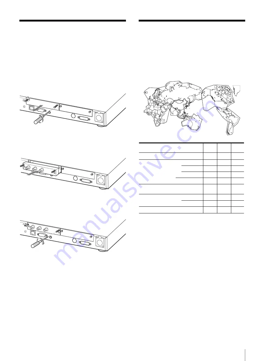
Attach the input adaptor to the optional input slot after 
removing the panel of the slot.

1

Remove the panel of the optional input slot.

2

Insert the input adaptor into the slot.

3

Tighten the screws.

Selecting the Default 
Settings

When you turn on the unit for the first time after 
purchasing it, select the area where you intend to use this 
unit from among the options.

The default setting values for each area

INPUT

MONITO

R OUT

INPUT

MONITO

R OUT

3

3

4

5

3

1

2

COLOR 

TEMP

COMP 
LEVEL

NTSC 

SETUP

1

NORTH AMERICA

Low

BETA7.5

7.5

2

LATIN AMERICA

PAL&PAL-N AREA

ARGENTINA

Low

SMPTE

0

PARAGUAY

Low

SMPTE

0

URUGUAY

Low

SMPTE

0

NTSC&PAL-M AREA

OTHER AREA

Low

BETA7.5

7.5

3

AFRICA AUSTRALASIA

EUROPE MIDDLE-EAST

Low

SMPTE

0

4

ASIA EXCEPT JAPAN

NTSC AREA

Low

BETA7.5

7.5

PAL AREA

Low

SMPTE

0

5

JAPAN

High

SMPTE

0

Summary of Contents for MEU-WX1

Page 1: ...4 098 710 16 1 Multiformat Engine Unit 2003 Sony Corporation MEU WX1 Operating Instructions ...

Page 2: ...und to comply with the limits for a Class A digital device pursuant to Part 15 of the FCC Rules These limits are designed to provide reasonable protection against harmful interference when the equipment is operated in a commercial environment This equipment generates uses and can radiate radio frequency energy and if not installed and used in accordance with the instruction manual may cause harmfu...

Page 3: ...oduct is installed in a rack please make sure that the internal air ambient temperature of the rack is within the specified limit of this product 4 Prevention against achieving hazardous condition due to uneven mechanical loading When this product is installed in a rack please make sure that the rack does not achieve hazardous condition due to uneven mechanical loading 5 Install the equipment whil...

Page 4: ...ch an einen autorisierten Sony Händler Dieses Gerät enthält Substanzen die bei unsachgemäßer Entsorgung die Umwelt belasten Bitten wenden Sie sich an unsere nächste Niederlassung oder an Ihr Umweltschutzamt wenn Sie das Gerät entsorgen wollen WARNUNG DIESES GERÄT MUSS GEERDET WERDEN Français Deutsch Warnhinweis zum Netzanschluss Verwenden Sie ein für die Stromversorgung in Ihrem Land geeignetes Ne...

Page 5: ...autele Per informazioni sulle normative in caso di smaltimento di questo apparecchio si prega di contattare il nostro rappresentatnte locale o il centro di informazioni ambientali di zona AVVERTENZA QUESTO APPARECCHIO DEVE ESSERE COLLEGATO A MASSA Español Italiano Avvertenza sul collegamento dell alimentazione Utilizzare un cavo di alimentazione adeguato all alimentazione del Paese in cui ci si tr...

Page 6: ...ngen E4 kontrollierter EMV Bereich z B Fernsehstudio Para los usuarios en Europa Este producto con la marca CE cumple con las Directivas EMC 89 336 CEE y de Baja Tensión 73 23 CEE emitidas por la Comisión de la Comunidad Europea El cumplimiento de estas directivas implica la conformidad con los siguientes estándares europeos EN60950 Seguridad del producto EN55103 1 Interferencias electromagnéticas...

Page 7: ...7 ...

Page 8: ...o the Rack 15 Connections 16 To Connect an LCD Monitor 16 To Connect the AC Power Cord 16 Attaching the Input Adaptor 17 Selecting the Default Settings 17 Selecting the Menu Language 19 Using the Menu 20 Adjustment Using the Menus 21 Items 21 Adjusting and Changing the Settings 22 STATUS menu 22 COLOR TEMP BAL menu 22 USER CONTROL menu 23 USER CONFIG menu 26 REMOTE PARALLEL menu 29 OPTION CONFIG m...

Page 9: ...throw away the carton and packing materials They make an ideal container which to transport the unit On Mounting on a Rack Leave 1U space empty above and below the monitor to ensure adequate air circulation or install a fan to maintain the monitor s performance If you have any questions about this unit contact your authorized Sony dealer On Fan Error The fan for cooling the unit is built in When t...

Page 10: ...ns APA Auto Pixel Alignment function You can display pictures from the computer in the appropriate size by simply pressing the APA button Select color temperature and gamma mode You can select the color temperature from among two high and low settings and gamma mode from among five settings You can also adjust the color temperature to the appropriate setting Aspect setting You can set the monitor ...

Page 11: ...crease it g APERTURE control Adjusts the picture sharpness Turn the control clockwise to increase the sharpness or counterclockwise to decrease it h Menu operation buttons Displays or sets the on screen menu M m arrow buttons Select the menu or make various adjustments MENU button Press to display the on screen menu Press again to clear the menu RESET button Resets the value of an item back to the...

Page 12: ...on Sets the aspect ratio of the picture 4 3 or 16 9 Note When a 16 9 signal is displayed black bars appear in the upper and lower positions of the display because the screen size is 15 9 This is not a malfunction See SCAN on page 27 28 n MARKER button When the button is pressed an area marker is displayed Set the safety area size in the menu screen o BLUE ONLY button Press this button to eliminate...

Page 13: ... 255DV is attached Input signal Item Video Y C B W Component RGB SDI DV 6 Computer SD HD SD HD D1 4 HD 5 CONTRAST 1 a a a a a a a a a a BRIGHT 1 a a a a a a a a a a CHROMA 1 a a a a a a PHASE 1 a NTSC APERTURE a a a a a a a COLOR TEMP a a a a a a a a a a AUTO CHROMA PHASE a a a a a a ACC a CTI a a V SHARPNESS 2 a a a a a a MATRIX 3 a COMP LEVEL a 480 60I NTSC SETUP a NTSC a 480 60I GAMMA a a a a a...

Page 14: ...5 ohm termination of the input is automatically released and the signal input to the IN connector is output from this connector e AUDIO IN connector stereo mini jack Connect to the audio outputs of a VCR or to a audio mixer f Optional input slot An optional input adaptor can be attached according to your requirements Press the A 1 A 2 B 1 or B 2 button to select the signal g AC IN socket Connect t...

Page 15: ...TER AUDIO connector stereo mini jack Connect to the audio output connector of the computer n Service terminal This connector is for use by service personnel only o DISPLAY SIGNAL OUT connector Connect a suitable monitor Connect to the LCD monitor by using the cable supplied with the LCD monitor Specified monitors LMD 150 LMD 170W LMD 171W LMD 230W LMD 210 LMD 320W p DISPLAY DC OUT connector XLR fe...

Page 16: ...r When connecting LMD 320W connect the DISPLAY SIGNAL connector only To Connect the AC Power Cord Connect the supplied AC power cord as illustrated 1 Plug the AC power cord into the AC IN socket on the rear panel Then attach the AC plug holder supplied to the AC power cord 2 Slide the AC plug holder over the cord until it locks To remove the AC power cord Pull out the AC plug holder while pressing...

Page 17: ...ettings When you turn on the unit for the first time after purchasing it select the area where you intend to use this unit from among the options The default setting values for each area INPUT MONITOR OUT INPUT MONITOR OUT 3 3 4 5 3 1 2 COLOR TEMP COMP LEVEL NTSC SETUP 1NORTH AMERICA Low BETA7 5 7 5 2LATIN AMERICA PAL PAL N AREA ARGENTINA Low SMPTE 0 PARAGUAY Low SMPTE 0 URUGUAY Low SMPTE 0 NTSC P...

Page 18: ... SETTING screen disappears and the menu item settings suitable for the selected area are applied Note When you have selected the wrong area set the following items using the menu See The default setting values for each area page 17 on the setting value COLOR TEMP on page 22 COMP LEVEL on page 26 NTSC SETUP on page 26 S E L E C T S E T T I N G xN O R T H A M E R I C A L A T I N A M E R I C A A F R ...

Page 19: ...figuration 1 2 menu then press the or ENTER button The setting items icons in the selected menu are displayed in yellow 4 Press the M or m button to select LANGUAGE then press the or ENTER button The selected item is displayed in yellow 5 Press the M or m button to select a language then press the ENTER button The menu changes to the selected language To clear the menu Press the MENU button The me...

Page 20: ...rease the number press the M or button To decrease the number press the m or button Press the ENTER button to confirm the number then restore the original screen When changing the setting Press the M or m button to change the setting Press the ENTER button to confirm the setting Notes An item displayed in blue cannot be accessed You can access the item if it is displayed in white If the key inhibi...

Page 21: ...UTION fH fV COLOR TEMP GAMMA POWER SAVING DISPLAY MULTI FORMAT ENGINE OPTION A OPTION B COLOR TEMP BAL COLOR TEMP MANUAL ADJ USER CONTROL When selecting an input other than COMPUTER AUTO CHROMA PHASE SUB CONTROL PICTURE CONTROL INPUT SETTING When selecting the COMPUTER input SUB CONTROL INPUT SETTING USER CONFIG MATRIX COMP LEVEL NTSC SETUP GAMMA FORMAT DISP LANGUAGE AUDIO IN POWER SAVING MARKER C...

Page 22: ...x STATUS 1 2 Rr DISPLAY LMD 230W xxxxxxx MULTIFORMAT ENGINE MEU WX1 xxxxxxx OPTION A BKM 220D xxxxxxx OPTION B NOT INSTALLED STATUS 2 2 Rr MEM NO xxxx RESOLUTION xxxxxxxx fH xxxxxxx fV xxxxx COLOR TEMP xxxx GAMMA x POWER SAVING xx STATUS 1 2 Rr DISPLAY LMD 230W xxxxxxx MULTIFORMAT ENGINE MEU WX1 xxxxxxx OPTION A BKM 220D xxxxxxx OPTION B NOT INSTALLED STATUS 2 2 Rr Submenu Setting COLOR TEMP Selec...

Page 23: ...n finely adjust the adjustment range of the following controls on the front panel CONTRAST BRIGHT CHROMA and PHASE controls CONTRAST Adjusts the picture contrast BRIGHT Adjusts the picture brightness CHROMA Adjusts color intensity The higher the setting the greater the intensity The lower the setting the lower the intensity PHASE Adjusts color tones The higher the setting the more greenish the pic...

Page 24: ...higher the setting the larger the horizontal size of the picture The lower the setting the smaller the horizontal size of the picture SHIFT H Adjusts the position of the picture As the setting increases the picture moves to the right and as the setting decreases the picture moves to the left SHIFT V As the setting increases the picture moves up and as the setting decreases the picture moves down D...

Page 25: ...rt display No Preset signal fH kHz fV Hz Dot Clock MHz Sync polarity Horizontal Vertical P01 640 480 VGA mode 3 31 469 59 940 25 175 Negative Negative P02 VGA VESA 75Hz 37 500 75 000 31 500 Negative Negative P03 VGA VESA 85Hz 43 269 85 008 36 000 Negative Negative P04 VGA non CRT 29 531 59 780 23 625 Positive Negative P05 800 600 SVGA VESA 60Hz 37 879 60 317 40 000 Positive Positive P06 SVGA VESA ...

Page 26: ...ong 5 settings When 3 is selected the setting is roughly same as the gamma mode of the CRT 2 2 FORMAT DISP Select the display mode of the signal format and scan mode ON The mode is always displayed OFF The display is hidden AUTO The format is displayed for about 10 seconds and scan mode is displayed for about 3 seconds when the input of the signal begins LANGUAGE You can select the menu or message...

Page 27: ...PAL 480 60I or 575 50I signal is input OFF Mode for giving precedence to the picture quality It takes longer than 1 or 2 for processing the picture 1 The processing time is short and this is a mode suitable for an animation Even when the picture is constructed by one field such as the proxy picture of XDCAM a smooth picture is displayed 2 The processing time is short and this is a mode suitable fo...

Page 28: ...When a 4 3 monitor is used When a 15 9 monitor is used Input Output ZEROSCAN NORMAL SCAN 5 OVERSCAN FULL ZOOM SD signal HD singal 4 3 16 9 16 9 Input Output ZEROSCAN NORMAL SCAN 5 OVERSCAN FULL ZOOM SD signal HD Signal 4 3 16 9 16 9 ...

Page 29: ... function you need to connect cables For more details see page 31 OPTION CONFIG menu Sets an optional input adaptor KEY INHIBIT menu You can lock the setting so that they cannot be changed by an unauthorized user Select OFF or ON If you set ON all items are displayed in blue indicating the items are locked x1PIN xxxxx 2PIN xxxxx 3PIN xxxxxxx 4PIN xxxxxxx 6PIN xxxxxxxx 7PIN xxxxxxxxx 8PIN xxxx REMO...

Page 30: ...andard color bar signal Composite input 1 Vp p 3dB sync negative Y C input Y 1 Vp p 3dB sync negative C 0 286 Vp p 3dB NTSC burst signal level 0 3 Vp p 3dB PAL burst signal level Audio input Stereo mini jack 1 5 dBu2 47 kilohms or higher External synchronized input connector BNC type 1 0 3 to 4 Vp p bipolarity ternary or negative polarity binary Remote input terminal Parallel remote Modular connec...

Page 31: ...ches w h d Mass Approx 4 5 kg 9 lb 15 oz Operating conditions Temperature0 C to 35 C 32 F to 95 F Recommended temperature 20 C to 30 C 68 F to 86 F Humidity 30 to 85 no condensation Pressure 700 hPa to 1060 hPa Storage and transport conditions Temperature 10 C to 40 C 14 F to 104 F Humidity 0 to 90 Pressure 700 hPa to 1060 hPa Accessories supplied AC power cord 1 AC plug holder 1 Mounting bracket ...

Page 32: ... 525 483 30 2 1 interlace 16 9 4 3 SMPTE 253M NTSC SMPTE 170M 576 50P 625 576 50 Progressive 16 9 4 3 ITU R BT 1358 480 60P 525 483 60 Progressive 16 9 4 3 SMPTE 293M 1080 24PsF 1 1125 1080 24 2 1 interlace 16 9 SMPTE RP211 1080 50I 1125 1080 25 2 1 interlace 16 9 SMPTE 274M 1035 60I 2 1125 1035 30 2 1 interlace 16 9 SMPTE 260M BTA S 001B 1080 60I 1125 1080 30 2 1 interlace 16 9 SMPTE 274M BTA S 0...

Page 33: ...A slightly squashed picture is displayed at a little lower position because the picture is displayed in 1035 1080 picture ratio on a 16 9 screen Adjust the position to the center using the SHIFT V setting on page 23 Dimensions Input System Signal standard BKM 220D BKM 243HS 575 50I ITU R BT 656 a a 480 60I SMPTE 259M a a 1080 24PsF 1 SMPTE 292M a 1080 50I SMPTE 292M a 1035 60I 2 SMPTE 292M a 1080 ...

Page 34: ...Sony Corporation ...

Reviews: