31
11. Fan Operation
Hall
1
2
3
Fan
Circuit
Infinity
Fan terminals =
1.7Meg ohms with
ohmmeter's 1.5v
battery
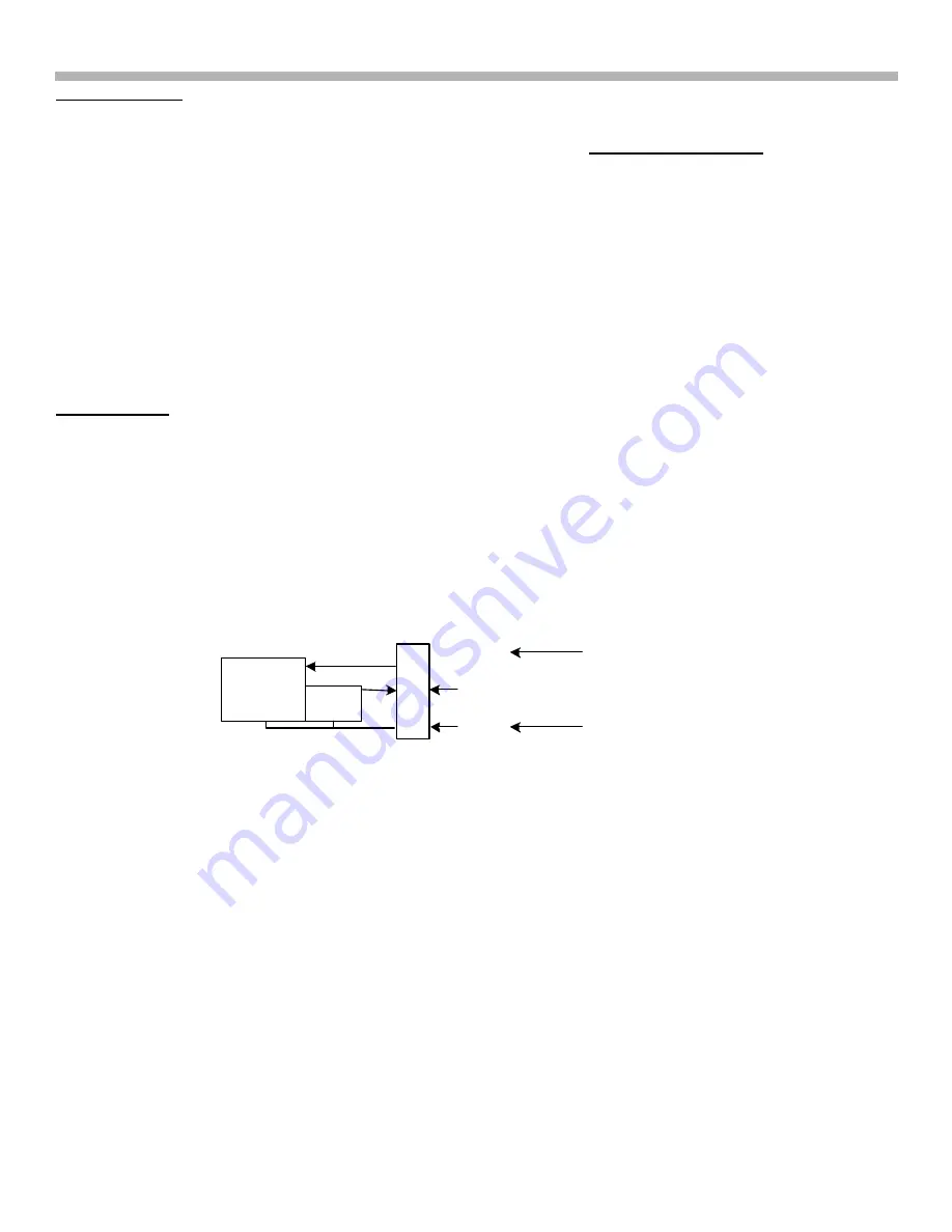
FIGURE 11-2 - FAN RESISTANCE TESTS
red
blue
Fan or Q board?
To determine if the fan, Q board or B board is causing NO fan rotation, turn ON the TV and:
1. Measure the voltage at the fan connector CN3009/pin 1 (red wire) with the fan connected (loaded).
2. Normal 12Vdc means the fan is bad. Replace the fan.
3. CN3009/pin 1= 0Vdc? You must inspect CN3005/pin 1 and CN1001/pin 24 at power ON.
•
CN3005/pin 1 on the power supply board normally = 13Vdc
•
CN1001/pin 24 on the B board normally = 5V pulse at power ON. The pulse can be read with a peak
DVM.
4. Is CN3005/pin 1, 0Vdc? Replace the power supply board.
5. Is CN1001/pin 24 at 0Vdc or stays at 5Vdc at power ON?
•
5Vdc at CN1001/pin 24 during power ON means the B board is OK so the Q board is bad.
•
0Vdc at CN1001/pin 24 during power ON means the B board is bad. Replace the B board.
Testing the fan
The fan should be tested by applying voltage to it.
Voltage Test:
The fan starts running when 6Vdc is applied (0.1A). You can also quickly start it using a 9V battery. Apply the
positive voltage to the red wire and negative to the blue wire.
Resistance Test:
A resistance check will only show you that a fan is not shorted. Resistance readings will not tell you if the fan will
run with voltage applied. Applying the ohmmeter positive leads produces these high resistances. Reversing the
leads permits you to read a diode in the Hall device.


