background image

– 15 –

SE-1

RM-ED007

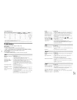
PC Input Signal Reference Chart

• This TV’s PC input does not support Sync on Green or Composite Sync.
• This TV’s PC input does not support interlaced signals.
• This TV’s PC input supports signals in the above chart with a 60 Hz vertical frequency. For other signals, you will see the 

message “NO SYNC”.

Troubleshooting

Check

 w

hether


the


1

 (

stand

b

y

indicator


is


flashing


in


red

.

When it is flashing

The self-diagnosis function is activated. 

1

Measure


ho

long


the


1

 (

stand

b

y

indicator


flashes


and


stops


flashing

.

For example, the indicator flashes for two seconds, stops flashing for one second, and flashes for two seconds.

2

Press


1


on


the


TV

 (

top


side

to


s

w

itch


it


off

disconnect


the


mains


lead

and


inform


your


dealer


or


Sony


ser

v

ice


centre


of


ho

the


indicator


flashes

 (

duration


and


inter

v

al

).

When it is not flashing
1

Check


the


items


in


the


ta

b

les

 b

elo

w.

2

I

f


the


pro

b

lem


still


persists

ha

v

e


your


TV


ser

v

iced

 b

y

 q

ualified


ser

v

ice


personnel

.

Signals

Horizontal (Pixel) Vertical (Line)

Horizontal 
frequency (kHz)

Vertical 
frequency (Hz)

Standard

VGA

640

480

31.5

60

VGA

SVGA

800

600

37.9

60

VESA Guidelines

XGA

1024

768

48.4

60

VESA Guidelines

WXGA

1280

768

47.4

60

VESA

1280

768

47.8

60

VESA

Picture

Problem

Cause/Remedy

No


picture

 (

screen


is


dark

and


no


sound

• Check the aerial connection.
• Connect the TV to the mains, and press 

1

 on the TV (top side).

• If  the 

1

 (standby) indicator lights up in red, press 

"

/

1

.

No


picture


or


no


menu


information


from


e

q

uipment


connected


to


the


scarts


or


HD

M

I I

N


socket

• Check that the optional equipment is on and press 

/

 repeatedly until 

the correct input symbol is displayed on the screen.

• Check the connection between the optional equipment and the TV.
• When connecting any equipment to the HDMI IN 6, 7 socket or when 

changing the resolution, some dots can appear blinking on the screen for a 
few seconds.  HDMI signal decoding is in progress and it does not indicate a 
malfunction.

D

ou

b

le


images


or


ghosting

• Check aerial/cable connections.
• Check the aerial location and direction.

Only


sno

and


noise


appear


on


the


screen

• Check if the aerial is broken or bent.
• Check if the aerial has reached the end of its serviceable life (three to five 

years in normal use, one to two years at the seaside).

D

istorted


picture

 (

dotted


lines


or


stripes

)

• Keep the TV away from electrical noise sources such as cars, motorcycles, 

hair-dryers or optical equipment.

• When installing optional equipment, leave some space between the optional 

equipment and the TV.

• Make sure that the aerial is connected using the supplied coaxial cable.
• Keep the aerial cable away from other connecting cables.

Picture


noise

 w

hen

 v

ie

w

ing


a


TV


channel

• Select “Manual Programme Preset” in the “Set-Up” menu and adjust “AFT” 

(Automatic Fine Tuning) to obtain better picture reception (page 21).

Some


tiny

 b

lack


points


and

/

or


b

right


points


on


the


screen

• The picture of a display unit is composed of pixels. Tiny black points and/or 

bright points (pixels) on the screen do not indicate a malfunction.

No


colour


on


programmes

• Select “Reset” in the “Picture Adjustment” menu to return to the factory 

settings (page 17).

No


colour


or


irregular


colour


w

hen

 v

ie

w

ing


a


signal


from


the


Y, 

P

B

/

C

B

P

R

/

C

R

 j

acks


of


3

• Check the connection of the Y, P

B

/C

B

, P

R

/C

R

 jacks of 

3.

• Make sure that the Y, P

B

/C

B

, P

R

/C

R

 jacks of 

3 are firmly seated in their 

respective sockets.

I

rregular


picture

 w

hen

 v

ie

w

ing


a


signal


from


PC

• Check PC input socket connection.
• Connect to PC input socket instead of HDMI IN 6, 7 socket.
• If the connection is only available through HDMI socket, change the screen 

resolution to 720p and adjust horizontal and vertical screen size in the 
display properties settings of PC.

Sound

Problem

Cause/Remedy

No


sound

, b

ut


good


picture

• Press 

2

 +/– or 

%

 (Mute).

• Check that “TV Speakers” is set to “On” in the “Sound Adjustment” menu 

(page 18).

Noisy


sound

• See the “Picture noise” causes/remedies on page 27.

Channels

Problem

Cause/Remedy

The


desired


channel


cannot

 b

e


selected

• Switch between digital and analogue mode and select the desired digital/

analogue channel.

Some


channels


are

 b

lank

• Scrambled/Subscription only channel. Subscribe to the Pay Per View 

service.

• Channel is used only for data (no picture or sound).
• Contact the broadcaster for transmission details.

D

igital


channel


is


not


displayed

• Check that the aerial is plugged directly into the TV (not through other 

equipment).

• Contact a local installer to find out if digital transmissions are provided in 

your area.

• Upgrade to a higher gain aerial.

General

Problem

Cause/Remedy

The


TV


turns


off


automatically


(

the


TV


enters


stand

b

y


mode

)

• Check if the “Sleep Timer” is activated, or confirm the setting of “Off 

Time” (page 20).

• If no signal is received and no operation is performed in the TV mode for 

10 minutes, the TV automatically switches to standby mode.

The


TV


turns


on


automatically

• Check if the “On Time” is activated (page 20).

Some


input


sources


cannot

 b

e


selected

• Select “AV Preset” in the “Set-up” menu and cancel “Skip” of the input 

source (page 20).

The


remote


does


not


function

• Replace the batteries.

Problem

Cause/Remedy

Summary of Contents for KDL-26P2520

Page 1: ...K KDL 32P2520 RM ED007 UK KDL 26P2530 RM ED007 UK KDL 32P2530 RM ED007 UK KDL 40P2530 RM ED007 UK RM ED007 FLAT PANEL COLORTV KDL 26P2520 KDL 32P2520 KDL 26P2530 KDL 32P2530 KDL 40P2530 KDL 26P2520 RM ED007 AEP KDL 32P2520 RM ED007 AEP KDL 26P2530 RM ED007 AEP KDL 32P2530 RM ED007 AEP KDL 40P2530 RM ED007 AEP ...

Page 2: ...4 BDTR 2 Printed Wiring Board 44 G1 Board Schematic Diagram KDL 26 32P2520 30 46 G1 Printed Wiring Board KDL 26 32P2520 30 48 G2 Board Schematic Diagram KDL 40P2530 50 G2 Printed Wiring Board KDL 40P2530 52 H1 H1P Board Schematic Diagram 54 H1 H1P Printed Wiring Board 55 H2 H2P Board Schematic Diagram 54 H2 H2P Printed Wiring Board 55 H3 H3P Board Schematic Diagram 54 H3 H3P Printed Wiring Board 5...

Page 3: ... following part numbers Due to the higher melting point of Lead Free Solder the soldering iron tip temperature needs to be set to 370 degrees centigrade This requires soldering equipment capable of accurate temperature control coupled with a good heat recovery characteristics For more information on the use of Lead Free Solder please refer to http www sony training com r e b m u n t r a P r e t e ...

Page 4: ... Inputs for RGB Outputs of Video and Audio signals Selectable SmartLink interface Dimensions KDL 26P2520 P2530 Approx 663x503x220mm With stand Approx 663x472x128mm Without stand KDL 32P2520 P2530 Approx 797x580x220mm With stand Approx 797x548x125mm Without stand KDL 40P2530 Approx 988x687x270mm With stand Approx 988x653x128mm Without stand Weight KDL 26P2520 P2530 Approx 12kg With stand Approx 10k...

Page 5: ... IN YOUR HOME IT SHOULD BE CUT OFF AND AN APPROPRIATE PLUG FITTED THE PLUG SEVERED FROM THE MAINS LEAD MUST BE DESTROYED AS A PLUG WITH BARED WIRES IS DANGEROUS IF ENGAGED IN A LIVE SOCKET When an alternative type of plug is used it should be fitted with a 10AMP FUSE otherwise the circuit should be protected by a 10AMP FUSE at the distribution board Model Name Item AEP UK PAP OFF OFF PAT OFF OFF R...

Page 6: ... rms Output impedence More than 10kohm 3 Audio output A left Standard level 0 5V rms Output impedence Less than 1kohm 4 Ground audio 5 Ground blue 6 Audio input A left Standard level 0 5V rms Output impedence More than 10kohm 7 Blue input 0 7 3dB 75 ohms positive 8 Function select AV control High state 9 5 12V Part mode Low state 0 2V TV mode Input impedence More than 10K ohms Input capacitance Le...

Page 7: ...mal mode Goes into standby LED flashes 4 times NVM Error 05 In Initialisation state Adds error to Error Menu LED flashes 5 times in factory mode IIC Error 06 In Initialisation state Adds error to Error Menu LED flashes 6 times in factory mode HDMI Error 07 In Initialisation state Adds error to Error Menu LED flashes 7 times in factory mode Digital Error 08 In Initialisation state Adds error to Err...

Page 8: ...ther or mix old and new batteries Handle the remote with care Do not drop or step on it or spill liquid of any kind onto it Do not place the remote in a location near a heat source or in a place subject to direct sunlight or in a damp room 2 Connecting an aerial VCR Connecting an aerial only Connecting an aerial and VCR Coaxial cable not supplied Scart lead not supplied VCR RF lead not supplied 3 ...

Page 9: ... all the available channels Auto Start Up Language Country Select Confirm Auto Start Up Language Country Select Confirm 1 3 Back Start Cancel MENU Overview of the TV buttons and indicators 1 MENU page 16 2 Input select OK In TV mode page 23 Selects the input source from equipment connected to the TV sockets In TV menu Selects the menu or option and confirm the setting 3 2 G g Increases or decrease...

Page 10: ...anual timer REC then press 3 Press F f to select the date then press g 4 Set the start and stop time in the same way as in step 3 5 Press F f to select the programme then press to set the TV and your VCR timers A symbol appears by that programme s information The indicator on the TV front lights up Navigating through menus MENU allows you to enjoy various convenient features of this TV You can eas...

Page 11: ...mic Intensifies clarity and sound presence for better intelligibility and musical realism by using the BBE High definition Sound System BBE ViVA BBE ViVA Sound provides musically accurate natural 3D image with Hi Fi sound The clarity of the sound is improved by BBE while the width depth and height of sound image are expanded by BBE s proprietary 3D sound process BBE ViVA Sound is compatible with a...

Page 12: ...hancer AV2 Output RGB Center PC Adjustment Timer Set up menu Timer Sets the timer to turn on off the TV Sleep Timer Sets a period of time after which the TV automatically switches itself into standby mode When the Sleep Timer is activated the Timer indicator on the TV front lights up in orange Tips If you switch off the TV and switch it on again Sleep Timer is reset to Off Sleep timer will end soo...

Page 13: ...rent software version and the signal level Time Zone Allows you to select the correct time zone for your country CA Module Set up Allows you to access a Pay Per View service once you obtain a Conditional Access Module CAM and a view card See page 23 for the location of the PCMCIA socket Set Up Select Enter Exit MENU English Back Auto Start Up Language Country Auto Tuning Programme Sorting AV Prese...

Page 14: ...nsions w h d KDL 40P25xx Approx 988 687 270 mm with stand Approx 988 653 128 mm without stand KDL 32P25xx Approx 797 580 220 mm with stand Approx 797 548 125 mm without stand KDL 26P25xx Approx 663 503 220 mm with stand Approx 663 472 128 mm without stand Mass KDL 40P25xx Approx 24 kg with stand Approx 21 kg without stand KDL 32P25xx Approx 15 kg with stand Approx 13 kg without stand KDL 26P25xx A...

Page 15: ...nt leave some space between the optional equipment and the TV Make sure that the aerial is connected using the supplied coaxial cable Keep the aerial cable away from other connecting cables Picture noise when viewing a TV channel Select Manual Programme Preset in the Set Up menu and adjust AFT Automatic Fine Tuning to obtain better picture reception page 21 Some tiny black points and or bright poi...

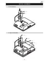
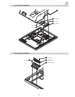
Page 16: ... 16 SE 1 RM ED007 SECTION 2 DISASSEMBLY 2 1 STAND REMOVAL 2 2 REAR COVER REMOVAL One screw Ten screws Rear Cover ...

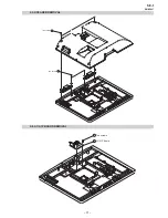
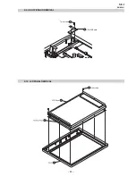
Page 17: ... 17 SE 1 RM ED007 2 3 SPEAKER REMOVAL 2 4 A1 A1P BOARD REMOVAL 1 Two screws 2 Two screws A1 A1P Board Two screws ...

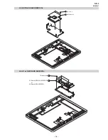
Page 18: ... 18 SE 1 RM ED007 2 5 BDTR 2 BOARD REMOVAL 2 6 G1 or G2 BOARD REMOVAL Two screws BDTR 2 Board Three screws G1 Board KDL 26 32P2520 30 or G2 Board KDL 40P2530 ...

Page 19: ... 19 SE 1 RM ED007 2 7 H1 H1P BOARD REMOVAL 2 8 H2 H2P BOARD REMOVAL H1 H1P Board Two screws H2 H2P Board Two screws Two screws ...

Page 20: ... 20 SE 1 RM ED007 2 9 H3 H3P BOARD REMOVAL 2 10 LCD PANEL REMOVAL H3 H3P Board Two screws Six screws LCD Panel ...

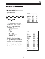
Page 21: ... OFF and then ON How to enter into the Service Mode 1 Turn on the main power switch 2 Press the following sequence of buttons on the Remote Commander 5 DIGIT 5 i ON SCREEN DISPLAY PROG These 3 buttons must be pressed together for approximately three seconds BACKLIGHT HDMI SOUND IF ADJUST ERROR MENU SE1T v0 06 Nov06 FACTORY DATA 11111111 SERIAL NUMBER 4294967295 WORKING TIME 0 22 BACKLIGHT BACKLIGH...

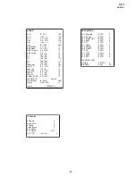
Page 22: ...0 127 5 30 3 30 5 40 0 2047 128 127 00000 192 20 20 10 10 496 1 0 3 0 4 0 12 12 6 23 0 0 0 5 3 5 2047 0 Status 0000000110 ERROR MENU E02 Reserved E03 DC Fail E04 PANEL DET E05 NVM E06 IIC E07 HDMI E08 DIGITAL E09 TUNER E10 SP E11 VCTP E12 PEXP E13 RTC WORKING TIME HOURS MINUTES 0 255 0 255 0 255 0 255 0 255 0 255 0 255 0 255 0 255 0 255 0 255 0 255 0 65535 0 59 0 0 0 0 0 0 0 0 0 0 0 0 0 38 IF ADJU...

Page 23: ... display toggle 37 Hotel mode toggle 38 OTRUM mode 39 Digital test toggle 41 Re initialise NVM 43 Dual Sound A 44 Dual Sound B 45 Dual Sound Mono 46 Dual Sound Stereo 48 Set NVM as non virgin CH59 only 49 Set NVM as virgin CH59 only 54 Watchdog toggle 55 Tuner toggle 56 Reset all channels attenuation 58 Chip select toggle 59 Visual I2C toggle 61 Auto AGC 63 AM from baseband toggle 64 Set 40 for A3...

Page 24: ...ue is shown when AM sound is demodulated in MSP A is shown when AFRIC demodulator is used TT63 14 S is shown when a SONY tuner is selected P is shown when a PHILIPS tuner is selected TT55 15 C is shown when a Chi Mei 20 panel is used S is shown when a Samsung panel is used A is shown when a AUO panel is used Changed by TT68 and TT69 for 26 and 32 respectively 3 is shown when a 40 Samsung A3 panel ...

Page 25: ...UNER SWITCH 16 3 Z Y X C B A X0 Y0 X1 Y1 VCC Z1 ANALOG AGC 5V STBY L1 SW1201 FILTER SURFACE WAVE L2 01 02 Q1201 SWITCH Q1202 SWITCH 10 SW1200 SAW FILTER 1 4 5 6 7 24 22 23 1 2 14 10 11 SDA 5V SCL 5V IC1200 IF PLL DEMODULATOR OP 2 SIF SIF VIF VIF TU AGC SDA SCL 17 VIDEO 3 OP 1 12 QSS 15 VCD Q1203 AMPLIFIER Q1204 BUFFER Q1205 AMPLIFIER C1226 L1201 TUNED CIRCUIT CVBS ANALOG RF X1200 ANALOG IF BLOCK A...

Page 26: ... RDATA 6 RDATA 7 RDATA 8 RDATA 9 RDATA 10 RDATA 11 RDATA 12 RDATA 13 RDATA 14 RDATA 15 BUF MDO CLK BUF MDO STRT BUF MDO EN IN TSD 0 IN TSD 1 IN TSD 2 IN TSD 3 IN TSD 4 IN TSD 5 IN TSD 6 IN TSD 7 IN TSBCLK IN TSBSYNC IN TSPVAL IC5680 NAND FLASH MEMORY 18 8 29 30 31 32 41 9 RDATA 0 42 43 44 FCSBO FWEB FOEB 7 16 17 RDATA 1 RDATA 2 RDATA 3 RDATA 4 RDATA 5 RDATA 6 RDATA 7 NAND CLE NAND ALE C15 D14 B13 ...

Page 27: ...2 TO A1 A1P BOARD CN2024 AUX MUX OUT R SIGNAL VCC SIGNAL VCC Q3020 BUFFER PANEL DET 40 PANEL DET 26 32 BACKLIGHT DIMMER SHEET 1 E TO G1 BOARD CN6003 KDL 26 32U2520 30 OR TO G2 BOARD CN6005 KDL 40U2530 LCD PANEL F4000 0 5A IC4000 EEPROM 6 SDA 5 SCL 5V STBY Q4214 SWITCH Q4213 SWITCH IN TSD 7 AGC DIGITAL IF DIGITAL IF DIGITAL SDA OFDM TUNER SCL OFDM TUNER SDA COFDM SCL COFDM nFE RESET SHEET 1 R SHEET...

Page 28: ...S6002 KDL 26 32P2520 30 ONLY POWER SUPPLY CN6001 3 1 A C IN N 11 1 CN6005 5 7 15 14 12 11 10 13 D6039 DIODE D6040 DIODE SIGNAL VCC 9 13 CN6003 TO H2 H2P BOARD CN9856 L IN R IN 2 3 IC6004 SHUNT RECTIFIER 8 10 5 2 3 1 PH6001 PHOTOCOUPLER 2 RY6000 R6017 Q6005 Q6006 SWITCHES 4 1 2 3 8 11 6 10 8 4 IC6200 STANDBY SWITCHING REGULATOR 2 5 7 2 3 PH6200 PHOTOCOUPLER 1 4 3 2 IC6201 SHUNT REGULATOR T6200 UP D...

Page 29: ... identifiés par une trame et par une marque sont d une importance critique pour la sécurité Ne les remplacer que par des pièces de numéro spécifié specified Note The components identified by shading and marked are critical for safety Replace only with the part numbers specified in the parts list Note CVM Board A Board S1 Board VM C H D1 A J A2 N D A1 D2 C A 4 2 CIRCUIT BOARD LOCATION 4 3 SCHEMATIC...

Page 30: ...W 1k 0 R2081 1 10W 470k R2064 25V 0 022 C2067 R2022 330 1 10W 10V 1 C2043 XX C2023 75 R2089 1 10W 25V 0 022 C2027 R2025 1 10W 1k 1 10W 470k R2066 10V 1 C2044 50V 1000p C2057 25V 0 022 C2065 100 R2070 1 10W 75 R2072 1 10W 1 10W 470k R2076 50V 1000p C2028 0 R2118 50V 1000p C2080 10V 1 C2074 D2059 UDZSTE 179 1B 1 10W 470k R2116 R2127 1 10W 1k L R J2022 XX C2051 R2074 1 10W 1k 10V 1 C2059 1 10W 470k R...

Page 31: ... C1217 AGC_DEFEAT 1 10W 270 R1234 10V 0 47 C1209 0 R1217 1 10W 220 R1222 XX C1215 16V 0 047 C1213 25V 0 01 C1206 25V 0 01 C1207 1 10W 1 2k R1230 16V 0 22 C1208 1 10W 2 2k R1204 1 10W 10k R1237 1 10W 100 R1220 1 10W 180 R1239 50V 22p C1216 25V 0 1 C1200 1 10W 100 R1224 MUN2213T1 Q1204 1 10W 3 3k R1214 D1203 XX IF_ANALOG MUN2213T1 Q1202 1 10W 6 8k R1229 50V 82p C1219 XX R1227 XX C1224 2SD601A Q TX Q...

Page 32: ...HT 20P CN2024 AGC_DEFEAT SV_STBY AUDIOMONO GND AU_MUX_OUT_R AU_MUX_OUT_L AU_MUX_CTRL_B AU_MUX_CTRL_A QSS GND LINEOUT_R LINEOUT_L GND L2 OUT R2 OUT GND L1 IN R1 IN GND L1 OUT R1 OUT XX R2144 0 R2145 5V_STBY XX R2148 0 R2147 BUFFER_V SC1 IN L SC1 IN R SC1 OUT L SC1 OUT R SC2 OUT L SC2 OUT R QSS V IN 2 MODE2 AV_LINK BLK2 V IN 1 MODE1 BLK1 RED 1 V OUT 2B BLUE 2 GREEN 2 RED 2 V OUT 1B BLUE 1 CVBS_ANALO...

Page 33: ...ble A1 A1P Printed Wiring Board Conductor Side B Ref No Pin No Volts V Ref No Pin No Volts V Ref No Pin No Volts V IC1000 1 3 7 IC1000 13 15 3 6 IC2000 8 4 2 2 3 2 16 5 0 9 8 5 3 4 2 3 IC2000 1 5 0 10 4 3 5 8 0 6 4 2 11 15 0 9 12 3 2 7 0 16 8 5 Ref e s b g c d Q2000 0 0 4 8 4 Q2001 0 0 7 0 A1 A1P Board SemiconductorVoltageTable ...

Page 34: ...DAT0 DSR0B PPORT43 AO1_DAT PPORT125 AO1_LRCK PPORT123 AO1_BCK PPORT124 AO1_MCK PPORT122 AO0_DAT AO0_LRCK AO0_BCK AO0_MCK ATX PAR PPORT56 FRAMEB PPORT57 IRDYB PPORT58 TRDYB PPORT59 STOPB PPORT60 IDSEL PPORT61 DEVSELB PPORT62 REQB0 PPORT63 GNTB0 PPORT64 PERRB PPORT65 VDOE_VCK_IN AD1 PPORT70 VDOE_VVSB_IN AD2 PPORT71 VDOE_VHSB_IN AD3 PPORT72 VDOE_VCK SERRB PPORT66 VDOE_VVSB_OUT INTAB PPORT67 VDOE_VHSB...

Page 35: ...53 56 1 49 50 51 2 55 54 52 3 4 5 6 7 8 47 10 46 45 44 43 42 11 12 13 14 15 41 40 39 38 37 36 35 16 17 18 19 20 21 22 34 33 23 24 32 25 31 30 29 26 27 28 57 58 59 60 61 62 63 64 65 66 IC5681 HYB25DC128169EE 6 VDD DQ0 VDDQ DQ1 DQ2 VSSQ DQ3 DQ4 VDDQ DQ5 DQ6 VSSQ DQ7 NC VDDQ LDQS NC VDD NC LDM WE CAS RAS CS NC BS0 BS1 A10 A0 A1 A2 A3 DQ15 VSS A4 A5 A6 A7 A8 A9 A11 A12 NC CKE CLK CLK UDM VSS VREF NC U...

Page 36: ...6B CE1B INPACKB FWEB nCI_EN FOEB BUF_MDO_EN CHIP 0 R5950 CHIP 0 R5951 3V3D_31 3V3D_31 3V3D_31 5VD_CI 3V3D_31 3V3D_31 3 3V_MAIN 3V3D_31 3V3D_31 3V3D_31 3V3D_31 3V3D_31 3V3D_31 IN_TSD 0 7 IN_TSBCLK IN_TSPSYNC IN_TSPVAL 20 19 18 17 16 15 14 13 12 11 10 9 8 7 6 5 4 3 2 1 TC74LCX541FT EKJ IC5758 OE1 A0 A1 A2 A3 A4 A5 A6 A7 GND Y7 Y6 Y5 Y4 Y3 Y2 Y1 Y0 OE2 Vcc XX R5952 XX R5953 10V 4 7 C5767 68 R5959 1 1...

Page 37: ...025 1YM IC5786 EN FLAG GND NC NC OUT IN OUT CI_PWR_EN DIGITAL_RF_R DIGITAL_RF_L nCI_OVR YC_C XX R5787 YC_Y Q5781 XX XX C5784 R5785 XX 10p C5782 1 16W R5782 220 Q5780 MSB709 RT1 CVBS 1k R5784 SDA 10 9 8 7 6 5 4 3 2 1 RV5C387A E2 FB IC5780 32KOUT SCL SDA INTRC VSS INTRA INTRB OSCOUT OSCIN VDD JL5780 1 10W 100 R5780 10V 0 1 C5787 1 10W 100 R5783 MA113 TX D5780 SCL 6 3V 47 C5789 1 10W 100 R5781 3 3IO ...

Page 38: ...93 TMS 5V_STBY JTAG_RESET SDA_5V 1 2 3 4 5 6 7 8 9 10 11 12 13 14 15 16 17 18 18P CN3008 GND TXD RXD RES VIN MD0 MD1 MD2 NC NC FEW NC DTTLOG VIN B INT RXD TXD GND 0 R5863 0 R5864 0 R5865 TXD1B JIG_MODE RXD1B_ECS R3045 0 XX R3025 DIMMER 5V_MAIN DIMMER2 8 7 6 5 4 3 2 1 NJM2904M IC3003 OUT1 IN1 IN1 VSS IN2 IN2 OUT2 VCC XX R3041 D3000 XX 68k R3040 1 10W 25V 1 C3009 XX C3401 XX R3407 XX C3400 XX R3057 ...

Page 39: ...3 3V_MAIN 3 3V_MAIN 3 3V_MAIN 3 3V_MAIN 3 3V_MAIN 1 2 3 4 5 6 7 8 9 10 BLK 10P CN5883 RXD1B_ECS JTRST JTDI JTCK NMI_EDINT JTMS JTDO I2C_TV I2C_COFDM DEBUG UARTS SERVICE MEMORY STICK CONNECTOR 3V3D PMSSCLK PMSDIO PMSBS PMSINS GND GND 3V3D EJTAG CONNECTION FIT FOR FIT FOR JTAG EJTAG COMPONENTS MARKED AS XX ARE NOT FITTED ON THIS MODEL VD4003 1 10W 47 R4000 EMI G XX FL002 XX FB6505 XX FB6503 PC_BLUE ...

Page 40: ... 4 7k R6568 MONITOR_L MONITOR_R 2200p C3201 2200p C3200 100 R3311 100 R3310 MONITOR_R MONITOR_L PORT_CS CHIP 0 R9032 20 25MHz X3000 10k R3193 1 10W 10k R3196 2SC4617R Q3002 2SC4617R Q3003 5V_STBY 220k R3022 220k R3026 220k R3021 220k R3027 220k R3023 220k R3028 220k R3024 220k R3032 0uH FB3099 1 10W 2 2k R3015 16V 100 C3072 1 10W 1k R3016 SIGNAL_VCC_P 1 2 3 4 5 6 7 8 9 10 11 12 13 14 15 16 17 18 1...

Page 41: ...10W 150k R6539 MMDL914T1 D6519 10uH L6503 25V 0 01 C6513 25V 470 C6508 8 5V_MAIN 25V 470 C6509 1 10W 10k R6511 0uH FB6501 25V C6520 0 1 UN2211 Q6501 C6516 4 7 25V 16V C6528 0 22 1 8LVDS 25V 0 1 C6515 1 8V_STBY PTZ TE25 5 6B D6514 PANEL5V_GND 5V_STBY C6527 XX 16V 1 C6551 XX R6527 PANEL5V_GND XX C6531 XX R6538 16V 1 C6549 MMDL914T1 D6504 8 5V_MAIN C6517 4 7 25V 10uH L6511 1 2 3 4 5 PQ1CY1032ZP IC650...

Page 42: ...1 SDA_OFDM_TUNER 100 R5050 IF_DIGITAL_ 3V3D_CO R6578 0 XX R6579 R6581 0 XX C6580 10V 1 C6581 XX R6576 R6577 0 3 3V_MAIN 1 8V_MAIN 16V 0 47 C6582 1 2V_MAIN D6522 XX 47 RB5041 R5056 0 XX R5059 JL5058 JL5059 JL5060 10k R5060 1 16W 10k R5058 1 16W 10k R5064 5 4 3 2 1 MM3141CNRE IC6505 5 4 3 2 1 IC6504 XX 100 R5051 1 16W 50V 22p C5062 50V 22p C5061 1 2 3 4 5 6 7 8 9 10 11 12 13 14 15 16 17 18 19 20 21 ...

Page 43: ...3 HDMI_D1 1 2 3 4 5 6 7 8 9 10 11 12 13 14 15 16 17 18 19 20 21 22 23 24 25 26 27 28 29 30 31 32 33 34 35 36 37 38 39 40 41 42 43 44 45 46 47 48 49 50 51 52 53 54 55 56 57 58 59 60 61 62 63 64 65 66 67 68 69 70 71 72 73 74 75 76 77 78 79 80 81 82 83 84 85 86 87 88 89 90 91 92 93 94 95 96 97 98 99 100 101 102 103 104 105 106 107 108 109 110 111 112 113 114 115 116 117 118 119 120 121 122 123 124 12...

Page 44: ...s V Ref No Pin No Volts V Ref No Pin No Volts V Ref No Pin No Volts V Ref No Pin No Volts V Ref No Pin No Volts V IC3001 1 3 3 IC3001 5 3 3 IC3002 6 8 0 IC3002 13 0 3 IC3008 1 0 IC3008 5 2 8 IC3008 10 2 8 IC3008 16 5 0 IC5682 4 0 2 1 6 6 1 6 9 10 0 4 14 3 2 2 4 6 6 7 0 4 11 13 0 IC5682 1 1 4 5 1 7 3 3 2 7 8 3 3 11 0 15 2 4 3 0 4 8 0 14 3 7 2 0 6 7 3 2 4 0 IC3002 1 5 2 4 12 3 2 16 4 9 4 4 6 9 4 9 1...

Page 45: ...A B C D E F G H I J K L M N 1 2 3 4 5 6 7 8 9 10 11 O 45 BDTR 2 Printed Wiring Board Conductor Side B ...

Page 46: ...RT1 Q6001 1 10W RN CP 10k R6050 CHIP 0 R6202 50V 47 C6205 1 10W RN CP 22k R6012 1 10W RN CP 22k R6048 1 4W FPRD R6051 0 47 CM6004 RN CP 1 2k R6057 1 10W XX L6201 1 10W 27k R6018 1 4 6 9 10 11 8 2 T6200 1 10W RN CP 1k R6052 25V 47 C6011 XX R6065 100uH L6200 D6009 MM3Z15VT1 1 10W RN CP 10k R6026 XX C6026 3P CN6000 WHT 450V 330 C6008 AUDIO_VCC PC123Y22JOOF PH6001 1 10W 22k R6061 1 10W RN CP 1k R6047 ...

Page 47: ...IN AUDIO_VCC AUDIO_VCC 1 10W 1k R6309 AUD_GND AV_GND 8 7 6 5 4 3 2 15 14 13 12 11 10 TDA7495S IC6300 L IN NC NC NC R IN NC SVR S_GND STBY M UTE PW_GND R OUT VCC L OUT PW_GND UDZSTE 175 6B D6300 XX R6310 XX R6311 XX R6301 XX R6312 D6301 XX R6300 R6302 R6305 FB6301 FB6302 FB6303 FB6304 0 JR6313 0 JR6314 0 JR6315 0 JR6316 25V 0 022 C6315 CHIP 0 R6313 1 10W 100k R6314 1 10W RN CP 100k R6315 1 10W 22k ...

Page 48: ...Wiring Board Conductor Side A DIODE D6014 D 5 IC IC6201 F 7 D6000 K 6 D6015 D 7 IC6000 I 3 IC6300 C 4 D6008 I 4 D6018 C 7 IC6001 G 3 TRANSISTOR D6011 E 6 D6202 I 7 IC6002 F 3 Q6003 I 5 D6013 D 7 D6203 H 6 IC6200 I 6 Q6004 H 5 G1 Board Semiconductor LocationTable Side A ...

Page 49: ...005 N 7 D6000 E 6 D6008 G 4 D6013 L 7 D6019 M 6 D6300 N 4 IC6002 J 3 Q6000 F 3 Q6006 M 7 D6004 F 3 D6009 H 5 D6014 K 5 D6200 F 6 D6302 M 5 IC6200 G 7 Q6001 I 3 Q6007 M 7 D6005 H 3 D6010 G 4 D6015 L 7 D6201 F 6 IC IC6201 J 7 Q6002 H 3 Q6302 N 4 D6006 H 4 D6011 K 6 D6016 L 4 D6202 G 7 IC6000 G 4 IC6300 M 4 Q6004 H 5 Q6303 M 5 G1 Board Semiconductor LocationTable Side B ...

Page 50: ...nt Mecha 403694821 A6007 D6035 D6035 1 D10SC6M 4012 D6039 D6036 D10SC6M 4012 D10SC6M 4012 D6037 D10SC6M 4012 D6038 D10SC6M 4012 D6035 1uH L6005 LHL08 1uH L6004 LHL08 25V 1500 C6071 XX L6006 D6010 XX XX C6072 1 10W R6002 220k 1 10W R6001 220k 1 10W R6007 220k 1 10W R6006 220k MMDL914T1 D6000 MMDL914T1 D6002 1 10W R6005 470k 1 10W R6008 470k MMDL914T1 D600 1 C6048 XX 16V C6051 0 1 2SC1623 L5L6 Q6010...

Page 51: ...N AUDIO_VCC AUDIO_VCC 1 10W 1k R6309 AUD_GND 8 7 6 5 4 3 2 15 14 13 12 11 10 TDA7495S IC6300 L IN NC NC NC R IN NC SVR S_GND STBY M UTE PW_GND R OU T VCC L OUT PW_GND UDZSTE 175 6B D6300 XX R6301 XX R6312 D6301 XX R6300 R6302 R6305 FB6301 FB6302 FB6303 FB6304 0 JR6313 0 JR6314 0 JR6315 0 JR6316 CHIP 0 R6313 1 10W 100k R6314 1 10W 100k R6315 1 10W 22k R6316 50V 22 C6316 MSD601 RST1 Q6302 1 10W 10k ...

Page 52: ...r Location Table Side A DIODE D6206 I 8 D6003 B 8 D6207 I 9 D6004 H 8 IC D6012 D 4 IC6001 F 5 D6028 H 4 IC6002 E 2 D6036 M 2 IC6003 G 3 D6037 K 2 IC6004 H 2 D6038 L 3 IC6200 I 7 D6039 K 3 IC6201 K 8 D6040 K 7 IC6300 K 8 D6043 K 6 TRANSISTOR D6044 K 6 Q6001 B 4 D6200 H 7 Q6002 C 4 D6203 H 8 Q6013 F 3 D6204 I 8 Q6014 G 3 ...

Page 53: ...IC6000 L 1 D6013 L 2 IC6001 H 5 D6014 L 3 IC6002 H 2 D6015 F 10 IC6003 F 3 D6017 M 3 IC6004 G 2 D6018 L 3 IC6200 E 7 D6019 M 1 IC6201 D 9 D6020 M 1 IC6300 C 9 D6021 J 2 TRANSISTOR D6023 H 5 Q6001 L 4 D6027 I 2 Q6002 L 4 D6028 G 4 Q6003 L 3 D6031 H 4 Q6004 M 3 D6032 G 4 Q6005 F 10 D6033 I 2 Q6006 F 10 D6035 D 2 Q6007 J 3 D6036 B 2 Q6008 J 2 D6037 C 2 Q6009 J 2 D6038 B 3 Q6010 J 2 D6039 C 3 Q6011 J ...

Page 54: ...0 SIRCS GND NC REC RESERVE GREEN_LED ON_TIMER STBY_LED NC STBY 5V GND XX R9312 1 10W 2 2k R9310 1 10W 560 R9309 REC RESERVE RED ON_TIMER AMBER RED GREEN H3 H3PLED SIRCS SIRCS RECEIVER CN3003 COMPONENTS MARKED AS XX ARE NOT FITTED ON THIS MODEL H3 SE 1 KDL 26 32P2520 30 H3P SE 1 KDL 40P2530 TO BDTR 2 BOARD 50V C9082 100p 50V 1000p C9079 DTZ10B D9038 16V 2 2 C9049 CHIP 0 R9116 10V C9041 0 47 1 10W 1...

Page 55: ... H1P PrintedWiring Board Conductor Side A H1 H1P PrintedWiring Board Conductor Side B H2 H2P PrintedWiring Board Conductor Side A H2 H2P PrintedWiring Board Conductor Side B H3 H3P PrintedWiring Board Conductor Side A H3 H3P PrintedWiring Board Conductor Side B ...

Page 56: ...E2 FA5501AN D1 TE1 LM3525MX H J5000395 LM393DT A M24C02 WMN6T B M24C32 WMN6T B ICS7150MLFT K9F2808U0C PCB0T CXA1875AM T4 IP4776CZ38 MC14052 BDR2 MC74LVX8053DTR2 MC74LVXT4053DTR2 MCZ3001DB MM1431ATT MM1431ATT CN NCP1117STAT3 PQ070XNA1ZPH PQ1CY1032ZP NJM2904M NJM3404AM T1 ...

Page 57: ... 57 PST3629UL TC7SH00FU T5RSOYJF RPM7140 H8 RV5C387A E2 FB STR A6169 TL1431CZ AP TC74LCX541FT EKJ TAR5S50 TE85R TC7S66FU TK11185CSCL G TDA7495S TDA9886TS V4 118 TDA9974AHS 8 C112 UPD61123F1 100 KA3 A ...

Page 58: ...2530UK AEP 2 674 183 01 VESA BRACKET 26 32P2520 30UK AEP 5 2 679 993 05 BRACKET A DIG 6 2 674 192 02 BRACKET TERMINAL SIDE 7 A 1242 773 A BDTR 2 BOARD COMPLETE 8 A 1247 112 A A1 BOARD COMPLETE 26 32P2520 30UK AEP A 1247 116 A A1P BOARD COMPLETE 40P2530UK AEP 9 8 597 585 10 TUNER FSS BTP HC401 10 A 1189 409 A H2 BOARD COMPLETE 26 32P2520 30UK AEP A 1202 964 A H2P BOARD COMPLETE 40P2530UK AEP 11 2 6...

Page 59: ...0P2530UK AEP 18 A 1247 113 A H3 BOARD COMPLETE 26 32P2520 30UK AEP A 1247 117 A H3P BOARD COMPLETE 40P2530UK AEP 19 2 674 189 02 GUIDE LIGHT 20 NOT SERVICEABLE PART 21 NOT SERVICEABLE PART 22 NOT SERVICEABLE PART 23 NOT SERVICEABLE PART 5 1 CHASSIS Cont REF NO PART NO DESCRIPTION REMARK REF NO PART NO DESCRIPTION REMARK 18 19 17 59 21 20 23 22 ...

Page 60: ... 02 FOOT STAND 55 2 580 644 01 SCREW KTP2 3X8 26 32P2520 30UK AEP 2 580 647 01 SCREW KTP2 4X12 40P2530UK AEP 56 2 580 640 01 SCREW BVTP2 4X16 57 2 021 173 12 COVER ECS 20 59 67 57 60 66 53 58 UK models only 54 54 56 55 56 55 55 62 63 64 65 51 52 68 61 58 2 667 973 02 COVER SERVICE C 59 1 832 132 11 POWER SUPPLY CORD 26 32P2520 30 40P2530AEP 60 1 832 170 11 POWER SUPPLY CORD UK PLUG 26 32P2520 30 4...

Page 61: ...n the Parts List 61 Page A1 A1P BOARD COMPLETE Parts List 62 H2 H2P BOARD COMPLETE Parts List 65 H3 H3P BOARD COMPLETE Parts List 66 G2 BOARD COMPLETE Parts List KDL 40P2530 only 66 H1 H1P BOARD COMPLETE Parts List 70 BDTR 2 BOARD COMPLETE Parts List 70 G1 BOARD COMPLETE Parts List KDL 26P2520 30 KDL 32P2520 30 only 81 MISCELLANEOUS 85 ACCESSORIES AND CONNECTORS 85 REMOTE COMMANDER 85 Note The BDT...

Page 62: ... 8 719 069 60 DIODE UDZSTE 179 1B D2040 8 719 069 60 DIODE UDZSTE 179 1B A1 A1P A 1247 112 A A1 Board Complete KDL 26 32P2520 KDL 26 32P2530 A 1247 116 A A1P Board Complete KDL 40P2530 2 586 040 02 SHIELD CASE IFOB MAIN 2 586 041 01 SHIELD CASE IFOB TOP CAPACITOR C1000 1 126 947 11 ELECT 47UF 20 00 35V C1001 1 164 156 11 CERAMIC CHIP 0 1UF 25V C1100 1 162 927 11 CERAMIC CHIP 100PF 5 00 50V C1102 1...

Page 63: ...414 580 21 INDUCTOR 100NH L1104 1 414 934 21 INDUCTOR 10UH L1105 1 414 580 21 INDUCTOR 100NH L1107 1 414 934 21 INDUCTOR 10UH L1200 1 414 934 21 INDUCTOR 10UH L1201 1 410 993 42 INDUCTOR 1UH L1223 1 410 509 11 INDUCTOR 10UH L2000 1 414 934 21 INDUCTOR 10UH TRANSISTOR Q1200 8 729 010 29 TRANSISTOR MSD601 RST1 Q1201 8 729 421 19 TRANSISTOR UN2213 Q1202 8 729 421 19 TRANSISTOR UN2213 Q1203 8 729 422 ...

Page 64: ...1 METAL CHIP 10K 5 1 10W R2020 1 216 833 11 METAL CHIP 10K 5 1 10W R2021 1 216 295 91 SHORT CHIP 0 R2022 1 216 815 11 METAL CHIP 330 5 1 10W R2023 1 216 049 11 RES CHIP 1K 5 1 10W R2024 1 216 815 11 METAL CHIP 330 5 1 10W R2025 1 216 049 11 RES CHIP 1K 5 1 10W R2026 1 216 022 00 RES CHIP 75 5 1 10W R2028 1 216 022 00 RES CHIP 75 5 1 10W R2029 1 216 022 00 RES CHIP 75 5 1 10W R2030 1 216 022 00 RES...

Page 65: ...RES CHIP 150 5 1 10W R2121 1 216 029 00 RES CHIP 150 5 1 10W R2122 1 216 025 11 RES CHIP 100 5 1 10W R2123 1 216 049 11 RES CHIP 1K 5 1 10W R2124 1 216 029 00 RES CHIP 150 5 1 10W R2125 1 216 029 00 RES CHIP 150 5 1 10W R2126 1 216 029 00 RES CHIP 150 5 1 10W A1 A1P H2 H2P R2127 1 216 049 11 RES CHIP 1K 5 1 10W R2129 1 216 864 11 SHORT CHIP 0 R2132 1 216 864 11 SHORT CHIP 0 R2134 1 216 840 11 META...

Page 66: ... 606 01 IC RPM7540 H8 TRANSISTOR Q9300 8 729 907 00 TRANSISTOR DTC114EU Q9301 8 729 907 00 TRANSISTOR DTC114EU Q9302 8 729 907 00 TRANSISTOR DTC114EU Q9303 8 729 907 00 TRANSISTOR DTC114EU RESISTOR R9300 1 216 820 11 METAL CHIP 820 5 1 10W R9301 1 216 819 11 METAL CHIP 680 5 1 10W R9306 1 216 817 11 METAL CHIP 470 5 1 10W R9307 1 216 805 11 METAL CHIP 47 5 1 10W R9309 1 216 818 11 METAL CHIP 560 5...

Page 67: ... 1UF 10 00 50V C6308 1 126 952 11 ELECT 1000UF 20 00 35V C6309 1 126 952 11 ELECT 1000UF 20 00 35V C6310 1 164 227 11 CERAMIC CHIP 0 022UF 10 00 25V C6311 1 164 227 11 CERAMIC CHIP 0 022UF 10 00 25V C6312 1 163 021 91 CERAMIC CHIP 0 01UF 10 00 50V C6313 1 163 021 91 CERAMIC CHIP 0 01UF 10 00 50V C6316 1 107 907 11 ELECT 22UF 20 50V CONNECTOR CN6001 1 691 960 11 PIN CONNECTOR PC BOARD 3P CN6003 1 7...

Page 68: ...TOR 2SC1623 L5L6 Q6007 8 729 120 28 TRANSISTOR 2SC1623 L5L6 Q6008 8 729 804 41 TRANSISTOR 2SB1122 S Q6009 8 729 120 28 TRANSISTOR 2SC1623 L5L6 Q6010 8 729 026 49 TRANSISTOR 2SA1037AK T146 R Q6011 8 729 120 28 TRANSISTOR 2SC1623 L5L6 Q6012 8 729 045 62 TRANSISTOR 2SK2158 T2B Q6013 6 551 545 01 TRANSISTOR 2SK3469 01MR F111 Q6014 6 551 545 01 TRANSISTOR 2SK3469 01MR F111 Q6302 8 729 010 29 TRANSISTOR...

Page 69: ... 216 009 91 RES CHIP 22 5 1 10W R6096 1 216 821 11 METAL CHIP 1K 5 1 10W R6097 1 216 833 11 METAL CHIP 10K 5 1 10W R6098 1 216 821 11 METAL CHIP 1K 5 1 10W R6099 1 216 009 91 RES CHIP 22 5 1 10W R6100 1 216 833 11 METAL CHIP 10K 5 1 10W R6101 1 216 833 11 METAL CHIP 10K 5 1 10W R6102 1 216 833 11 METAL CHIP 10K 5 1 10W R6103 1 218 879 11 METAL CHIP 22K 0 5 1 10W R6104 1 218 847 11 METAL CHIP 1K 0 ...

Page 70: ...ARISTOR CHIP 1608 VD9005 1 803 974 21 VARISTOR CHIP 1608 VD9006 1 803 974 21 VARISTOR CHIP 1608 A 1242 773 A BDTR 2 COMPLETE CAPACITOR C3001 1 125 891 11 CERAMIC CHIP 0 47UF 10 00 10V C3002 1 125 891 11 CERAMIC CHIP 0 47UF 10 00 10V C3003 1 125 891 11 CERAMIC CHIP 0 47UF 10 00 10V C3004 1 164 156 11 CERAMIC CHIP 0 1UF 25V C3005 1 125 891 11 CERAMIC CHIP 0 47UF 10 00 10V C3007 1 164 156 11 CERAMIC ...

Page 71: ... 00 50V C4253 1 162 964 11 CERAMIC CHIP 0 001UF 10 00 50V C4254 1 162 964 11 CERAMIC CHIP 0 001UF 10 00 50V C4255 1 162 964 11 CERAMIC CHIP 0 001UF 10 00 50V C3044 1 127 715 91 CERAMIC CHIP 0 22UF 10 16V C3045 1 107 826 11 CERAMIC CHIP 0 1UF 10 00 16V C3048 1 162 966 11 CERAMIC CHIP 0 0022UF 10 00 50V C3049 1 162 966 11 CERAMIC CHIP 0 0022UF 10 00 50V C3050 1 107 826 11 CERAMIC CHIP 0 1UF 10 00 16...

Page 72: ...CERAMIC CHIP 4 7UF 10V C5756 1 117 720 11 CERAMIC CHIP 4 7UF 10V C5761 1 164 937 11 CERAMIC CHIP 0 001UF 10 00 50V C5767 1 117 720 11 CERAMIC CHIP 4 7UF 10V C5782 1 164 850 11 CERAMIC CHIP 10PF 0 50PF 50V C5783 1 164 943 81 CERAMIC CHIP 0 01UF 10 00 16V C5789 1 126 205 11 ELECT CHIP 47UF 20 00 6 3V C5790 1 104 905 11 DOUBLE LAYER 0 22F 5 5V C5791 1 164 943 81 CERAMIC CHIP 0 01UF 10 00 16V C5792 1 ...

Page 73: ...CONNECTOR ZIF 49P CN3006 1 820 255 51 FFC FPC CONNECTOR ZIF 20P CN3007 1 784 254 11 CONNECTOR 10P CN3008 1 779 936 51 CONNECTOR FFC FPC 18P CN4000 1 817 804 11 CONNECTOR D SUB 15P CN4200 1 821 188 11 HDMI CONNECTOR CN4201 1 821 188 11 HDMI CONNECTOR CN5750 1 793 769 21 CONNECTOR CARD PCMCIA CARD CN5883 1 820 209 11 MEMORY STICK CONNECTOR CN6501 1 819 474 11 HEADER ASSEMBLY FOR PWB 6P BDTR 2 DIODE ...

Page 74: ...W T IC5780 6 700 108 01 IC RV5C387A E2 FB IC5781 6 703 271 01 IC TAR5S50 TE85R IC5782 6 707 808 01 IC WM8727GED RV IC5783 8 759 701 40 IC NJM3404AM T1 IC5784 6 706 106 01 IC NCP1117STAT3 FERRITE BEAD FB3012 1 414 445 11 FERRITE 0UH FB3013 1 414 445 11 FERRITE 0UH FB3014 1 414 445 11 FERRITE 0UH FB3016 1 414 760 21 FERRITE 0UH FB3046 1 414 445 11 FERRITE 0UH FB3099 1 414 760 21 FERRITE 0UH FB3241 1...

Page 75: ...2 026 11 INDUCTOR 1UH BDTR 2 L6515 1 412 026 11 INDUCTOR 1UH L6516 1 412 026 11 INDUCTOR 1UH L6517 1 414 394 11 INDUCTOR 2 2UH L6518 1 412 026 11 INDUCTOR 1UH L6519 1 412 026 11 INDUCTOR 1UH L6520 1 412 026 11 INDUCTOR 1UH L6521 1 412 026 11 INDUCTOR 1UH L6522 1 412 026 11 INDUCTOR 1UH L6523 1 412 026 11 INDUCTOR 1UH L6524 1 412 026 11 INDUCTOR 1UH L6525 1 412 026 11 INDUCTOR 1UH L6526 1 414 394 1...

Page 76: ...9 11 METAL CHIP 220K 5 1 10W R3028 1 216 849 11 METAL CHIP 220K 5 1 10W R3029 1 216 841 11 METAL CHIP 47K 5 1 10W R3030 1 216 833 11 METAL CHIP 10K 5 1 10W R3031 1 216 864 11 SHORT CHIP 0 R3032 1 216 849 11 METAL CHIP 220K 5 1 10W R3034 1 218 871 11 METAL CHIP 10K 0 5 1 10W R3035 1 216 864 11 SHORT CHIP 0 R3036 1 216 864 11 SHORT CHIP 0 R3037 1 216 864 11 SHORT CHIP 0 R3038 1 216 864 11 SHORT CHIP...

Page 77: ...L CHIP 100 5 1 10W R3175 1 216 864 11 SHORT CHIP 0 R3177 1 216 809 11 METAL CHIP 100 5 1 10W R3178 1 216 809 11 METAL CHIP 100 5 1 10W R3180 1 216 809 11 METAL CHIP 100 5 1 10W R3181 1 216 809 11 METAL CHIP 100 5 1 10W R3182 1 216 809 11 METAL CHIP 100 5 1 10W R3183 1 216 809 11 METAL CHIP 100 5 1 10W R3184 1 216 809 11 METAL CHIP 100 5 1 10W R3185 1 216 809 11 METAL CHIP 100 5 1 10W R3186 1 216 8...

Page 78: ...16 821 11 METAL CHIP 1K 5 1 10W R4203 1 216 821 11 METAL CHIP 1K 5 1 10W R4204 1 216 833 11 METAL CHIP 10K 5 1 10W R4205 1 218 871 11 METAL CHIP 10K 0 5 1 10W R4206 1 218 871 11 METAL CHIP 10K 0 5 1 10W R3263 1 216 825 11 METAL CHIP 2 2K 5 1 10W R3264 1 216 825 11 METAL CHIP 2 2K 5 1 10W R3265 1 218 957 11 RES CHIP 2 2K 5 1 16W R3266 1 216 817 11 METAL CHIP 470 5 1 10W R3267 1 216 825 11 METAL CHI...

Page 79: ... 5 1 16W R5060 1 218 965 11 RES CHIP 10K 5 1 16W R5061 1 218 941 81 RES CHIP 100 5 1 16W R5062 1 218 941 81 RES CHIP 100 5 1 16W R5063 1 218 941 81 RES CHIP 100 5 1 16W R5064 1 218 965 11 RES CHIP 10K 5 1 16W R5630 1 218 965 11 RES CHIP 10K 5 1 16W R5631 1 218 965 11 RES CHIP 10K 5 1 16W R5632 1 218 965 11 RES CHIP 10K 5 1 16W R5633 1 218 965 11 RES CHIP 10K 5 1 16W R5634 1 218 941 81 RES CHIP 100...

Page 80: ... CHIP 10K 5 1 16W R5862 1 218 965 11 RES CHIP 10K 5 1 16W R5885 1 218 965 11 RES CHIP 10K 5 1 16W R5886 1 218 965 11 RES CHIP 10K 5 1 16W R5887 1 218 961 11 RES CHIP 4 7K 5 1 16W R5888 1 218 965 11 RES CHIP 10K 5 1 16W R5889 1 218 961 11 RES CHIP 4 7K 5 1 16W R5890 1 218 965 11 RES CHIP 10K 5 1 16W R5891 1 218 961 11 RES CHIP 4 7K 5 1 16W R5892 1 218 965 11 RES CHIP 10K 5 1 16W R5893 1 218 965 11 ...

Page 81: ...RB4205 1 239 409 11 NETWORK RESISTOR CHIP 47 RB4206 1 239 409 11 NETWORK RESISTOR CHIP 47 RB4208 1 239 409 11 NETWORK RESISTOR CHIP 47 RB4209 1 239 409 11 NETWORK RESISTOR CHIP 47 RB4211 1 239 409 11 NETWORK RESISTOR CHIP 47 BDTR 2 G1 RB4212 1 239 409 11 NETWORK RESISTOR CHIP 47 RB4214 1 233 796 11 RES NETWORK 1608 RB4215 1 233 796 11 RES NETWORK 1608 RB4216 1 233 796 11 RES NETWORK 1608 RB4217 1 ...

Page 82: ...V C6302 1 164 230 11 CERAMIC CHIP 220PF 5 00 50V C6303 1 126 960 11 ELECT 1UF 20 00 50V C6304 1 128 952 31 ELECT 220UF 20 00 25V C6306 1 164 489 11 CERAMIC CHIP 0 22UF 10 00 16V C6307 1 115 339 11 CERAMIC CHIP 0 1UF 10 00 50V C6308 1 128 959 31 ELECT 1000UF 20 00 35V C6309 1 128 959 31 ELECT 1000UF 20 00 35V C6310 1 164 227 11 CERAMIC CHIP 0 022UF 10 00 25V C6311 1 164 227 11 CERAMIC CHIP 0 022UF ...

Page 83: ...4W R6205 1 243 725 21 METAL OXIDE 100K 5 1W R6206 1 216 817 11 METAL CHIP 470 5 1 10W R6207 1 216 821 11 METAL CHIP 1K 5 1 10W R6208 1 216 864 11 SHORT CHIP 0 R6209 1 216 839 11 METAL CHIP 33K 5 1 10W R6210 1 218 871 11 METAL CHIP 10K 0 5 1 10W R6211 1 218 871 11 METAL CHIP 10K 0 5 1 10W R6212 1 216 295 91 SHORT CHIP 0 G1 IC6300 8 759 831 57 IC TDA7495S COIL L6000 1 456 507 12 LINE FILTER COIL L60...

Page 84: ...9 11 RES CHIP 1K 5 1 10W R6313 1 216 864 11 SHORT CHIP 0 R6314 1 216 845 11 METAL CHIP 100K 5 1 10W R6315 1 216 845 11 METAL CHIP 100K 5 1 10W R6316 1 216 837 11 METAL CHIP 22K 5 1 10W R6317 1 216 833 11 METAL CHIP 10K 5 1 10W R6318 1 216 833 11 METAL CHIP 10K 5 1 10W TRANSFORMER T6000 1 445 026 11 CONVERTER TRANSFORMER PIT T6001 1 445 027 11 CONVERTER TRANSFORMER PIT T6200 1 443 312 11 TRANSFORME...

Page 85: ... 910 026 69 LVDS FIR SHLDS 30P 40P2530UK AEP CN3001 B PANEL 1 1 910 026 71 CONNECTOR ASSY 4P 40P2530UK AEP CN3002 B CN9000 H1 1 1 910 026 72 CONNECTOR ASSY 10P 40P2530UK AEP CN3003 B CN9300 H3 1 1 910 032 60 CONNECTOR ASSY 14P 32P2520 30UK AEP INVERTER CN6002 G1 CN3004 B 1 1 910 032 61 CONNECTOR ASSY 14P 26P2520 30UK AEP INVERTER CN6002 G1 CN3004 B 1 1 910 032 62 LVDS 30P 26 32P2520 30UK AEP CN300...

Page 86: ...9 927 542 01 Sony Corporation Sony UK Service Promotions Dept English 07AP7100 1 Printed in U K 2007 01 ...

Reviews: