ICD-UX71/UX71F/UX81/UX81F/UX91F
9
SECTION 3
TEST MODE
This set provides the checks given blow in TEST MODE.
Setting the TEST MODE
Turn on power to the set. Turn on [DPC] switch from the off state
while pressing [MENU] key and [
.
] button at the same time.
Exiting the TEST MODE
Turn off power.
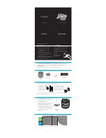
TEST MODE Menu
The menu given below appears when TEST MODE is entered.
Select an item using [
v
]/[
V
] key and determine the selected item
using [ENT] key.
1. Version
Check the version of each module.
ICD-UXx1 build: Language
(JP: Japanese, US: English, CN: Simpli
fi
ed Chi-
nese, CNS: Traditional Chinese, KR: Korean,
RU: Russian and TH: Thai)
(ICD-UX91 (4GB), ICD-UX81 (2GB), ICD-UX71 (1GB))
Charge: C (With), No display (Without)
F/W: Version
D: NAND DEVICE CODE
M: NAND Marker CODE
Destination: J, U, CE7, E, KR3, CN, CE7-FM, LA, LA-FM
2. Fmt
Check the input by pressing each key.
Input and INT check (KEY input acceptance check and KEY_
WAKE interrupt check).
Target input keys:
[
z
]/[
x
]/[
>
]/[
u
]/[
.
]/[A-B]/[MENU]/[VOL+]/[VOL–]/[
v
]/
ENT/[
V
]/DEVIDE/HOLD OFF
t
ON/DPC OFF
t
ON
Total of 15 key locations
The backlight is lit for 0.5 sec. when a key input is accepted.
When all the inputs have been con
fi
rmed at least once, format the
NAND
fl
ash memory (delete all entries) and set the MENU set-
tings to their defaults. (Hold the LCD contrast setting.)
* Once the NAND memory has been normally formatted, restart
the system.
3. Loop
Perform a ADDA LOOP BACK.
External mic input: HP/SP output change
HP INSERT: Change to L/H
ALC function: OFF
HP output is selected independent of whether HP is installed or not
when there is no external microphone (this is provided for anti-
howl back). Selection of HP or SP output is determined only upon
entry into Loop. There is no switching on the way.
[PLAY]: Loop Back Start
[VOL+], [VOL–]: Volume operation to set. (Initial value 20)
[DPC]: OFF: Sensitivity H, ON: Sensitivity L
[A-B]: External mic select (MIC IN
t
AUDIO IN)
4. SetMic Cal
Write the correction value for the level difference between L and R
channels of the internal stereo microphone into the NAND memo-
ry. With the L channel level as the reference, measure the R chan-
nel recording level. Then adjust the R channel’s ADC VOL level so
that the R channel level is equal to the L channel level.
* Make a mental note of the setting even when the battery has been
removed.
[PLAY]: Recording start
LCD display
Version
Fmt
Loop
Version
7
W
+
Datermine using ENT key.
Fmt
Loop
SetMic Cal
Beep
Lcd Cont
RTC Int
Battery
Batt AB4
VBUS TEST
MENU INIT
Sleep
Version
•
•
•
•
•
•
•
•
K
LCD display
<KEY CHECK>
KEY:
−
−
REMAIN: 15
Display the key of
which input is accepted.
Total of 15 keys counted.
LCD display
<Loop> MIC:L
Vol:20 MIC IN
LCD display
<SetMic Cal>
R-ch: –02dB
LCD display
ICD-UXx1 US C
F/W v1.10.02
D:D3 M:EC E


