21
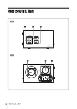
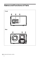
Names and Functions of Parts
a
POWER switch
Turns on or off the power. In the “
?
”
position, the power is on. In the “
a
”
position, the power is off.
b
ALARM indicator
Lights in red when an error occurs on
the unit or camera system.
c
CAM POWER indicator
Lights when the unit supplies power to
the camera/camcorder.
d
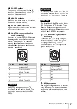
CAMERA connector (optical
multi connector)
Connect to the CA-FB70 HD Camera
Adaptor using an optical composite
cable. Power supply, all camera/
camcorder signals, such as control
signal, video signal and audio signal,
can be transmitted.
CAMERA connector is non LPS
(Limited Power Source) circuit. This
connector is connected to the CA-
FB70.
Le connecteur CAMERA n’est pas un
circuit LPS (Limited Power Source). Ce
connecteur est raccordé au CA-FB70.
Der Anschluss CAMERA ist ein Nicht-
LPS-Schaltkreis (LPS: Limited Power
Source, Spannungsversorgung mit
begrenzter Leistung). Dieser Anschluss
wird mit der CA-FB70 verbunden.
e
CCU connector (optical fiber
connector)
Connect to the CCU using a single-
mode optical fiber cable. All signals
(except power supply) can be
transmitted by a pair of single-mode
optical fiber cables.
f
AC IN connector
Use an optional power cord to connect
to an AC outlet. To fasten the power
cord to the unit, use an optional plug
holder.
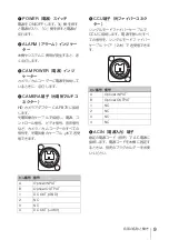
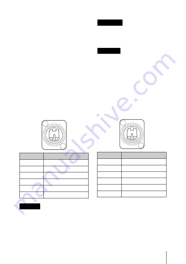
Pin No.
Signal name
A
Optical INPUT
B
Optical OUTPUT
1
DC OUT (GND)
2
NC
3
NC
4
DC OUT (+48 V)
CAUTION
ATTENTION
VORSICHT
Pin No.
Signal name
A
Optical INPUT
B
Optical OUTPUT
1
NC
2
NC
3
NC
4
NC
Summary of Contents for HXCE-FB70
Page 8: ...各部の名称と働き 8 各部の名称と働き 前面 背面 ...
Page 20: ...20 Names and Functions of Parts Names and Functions of Parts Front Rear ...
Page 26: ......
Page 27: ......
Page 28: ...Printed in Belgium ...

