background image

8

GB

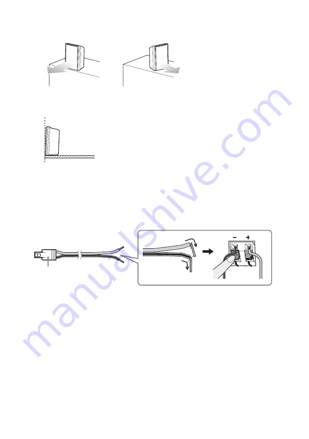
• Both speakers should be pointed straight forward. Do not place the speakers at an angle.

• It is recommended to place the speakers on the edge of a table or rack, etc., to prevent sound reflection.

To connect the speaker cords to the speakers

The connector of the speaker cords is color-coded depending on the type of speaker.
Connect the speaker cords to match the color of the SPEAKER jacks of the subwoofer.
Be sure to match the speaker cords to the appropriate terminals on the speakers: the gray speaker 
cord to 

+

, and the gray speaker cord with a black line to 

. Do not catch the speaker cord insulation 

in the speaker terminals.

Correct

Incorrect

Recommended

Side view

(–) Gray with
a black line

Connector
Speaker (L): White
Speaker (R): Red

Rear of the speaker

(+) Gray

Summary of Contents for HT-FS3

Page 1: ...Home Theatre System 2009 Sony Corporation 4 143 280 12 1 HT FS3 Operating Instructions ...

Page 2: ...ean countries with separate collection systems This symbol on the battery or on the packaging indicates that the battery provided with this product shall not be treated as household waste On certain batteries this symbol might be used in combination with a chemical symbol The chemical symbols for mercury Hg or lead Pb are added if the battery contains more than 0 0005 mercury or 0 004 lead By ensu...

Page 3: ...system Do not place the system near heat sources or in a place subject to direct sunlight excessive dust or mechanical shock Do not place anything at the rear of the subwoofer that might block the ventilation holes and cause malfunctions Do not cover the grill of the subwoofer Do not place the system near equipment such as a TV VCR or tape deck If the system is being used in combination with a TV ...

Page 4: ...Multimedia Interface are trademarks or registered trademarks of HDMI Licensing LLC BRAVIA Sync is a trademark of Sony Corporation PLAYSTATION is a trademark of Sony Computer Entertainment Inc S AIR and its logo are trademarks of Sony Corporation x v Colour x v Color and x v Colour x v Color logo are trademarks of Sony Corporation The system is compatible with the S AIR function which allows transm...

Page 5: ... mode 28 BRAVIA Sync Features What is BRAVIA Sync 29 Preparing for the BRAVIA Sync 29 Enjoying Blu ray Disc DVD 31 One Touch Play Enjoying the TV sound from the speakers 32 System Audio Control Turning off the TV system and connected components 33 System Power Off Using the power saving function 34 Tuner Functions Presetting radio stations 35 Listening to the radio 36 Using the Radio Data System R...

Page 6: ...casing particularly when replacing the batteries Do not expose the remote sensor to direct light from the sun or lighting apparatus Doing so may cause a malfunction If you do not intend to use the remote for an extended period of time remove the batteries to avoid possible damage from battery leakage and corrosion Getting Started Unpacking Subwoofer 1 Speakers 2 AM loop antenna aerial 1 FM wire an...

Page 7: ...the speakers efficiently Position the speakers so that the distance between each speaker and the listening position A and B is the same from 0 0 to 7 0 m Place both speakers the same distance apart as they are from the listening position to form an isosceles triangle The speakers should be placed at least 0 6 m apart Place the speakers forward of the TV Make sure there are no reflecting obstacles ...

Page 8: ...is color coded depending on the type of speaker Connect the speaker cords to match the color of the SPEAKER jacks of the subwoofer Be sure to match the speaker cords to the appropriate terminals on the speakers the gray speaker cord to and the gray speaker cord with a black line to Do not catch the speaker cord insulation in the speaker terminals Correct Incorrect Recommended Side view Gray with a...

Page 9: ...ng the speakers use the optional WS FV11 or WS FV10D speaker stand available only in certain countries For details refer to the operating instructions supplied with the speaker stand To install the speakers on a wall You can install your speakers on the wall 1 Prepare screws not supplied that are suitable for the hole on the back of each speaker See the illustrations below 2 Fasten the screws to t...

Page 10: ...o the wall Install the speakers on a vertical and flat wall where reinforcement is applied Contact a screw shop or installer regarding the wall material or screws to be used Sony is not responsible for accident or damage caused by improper installation insufficient wall strength or improper screw installation natural calamity etc Notes Rear of the speaker 4 6 mm 10 mm ...

Page 11: ...h the color of the SPEAKER jacks of the subwoofer Connecting the speakers ANTENNA AM FM 75 COAXIAL HDMI TV OUT SAT CATV IN DVD IN BD IN EZW T100 SPEAKER ONLY FOR SS FS3 R L DMPORT DC 5V 0 7A MAX AUDIO IN R TV L OPTICAL TV IN COAXIAL DIGITAL DIGITAL 1 IN DIGITAL 2 IN Speaker R Speaker L Red speaker R Rear of the subwoofer White speaker L ...

Page 12: ...using a digital optical cord or an audio cord in order to listen to the TV sound from the system The OPTICAL TV IN jack has priority when you connect both the audio output of the TV to the OPTICAL TV IN and AUDIO IN jack of the system Connecting components with HDMI jacks Note ANTENNA AM FM 75 COAXIAL HDMI TV OUT SAT CATV IN DVD IN BD IN EZW T100 SPEAKER ONLY FOR SS FS3 R L DMPORT DC 5V 0 7A MAX A...

Page 13: ...mponent is changed When the connected component is not compatible with copyright protection technology HDCP the image and or the sound from the HDMI TV OUT jack may be distorted or may not be output In this case check the specification of the connected component We do not recommend using an HDMI DVI conversion cable When TV DIGITAL 1 DIGITAL 2 FM AM or DMPORT is selected the video signal that was ...

Page 14: ...our components Connect the AC power cord mains lead last Connecting a component to the OPTICAL DIGITAL 1 IN jack Connecting components without HDMI jacks ANTENNA AM FM 75 COAXIAL HDMI TV OUT SAT CATV IN DVD IN BD IN EZW T100 SPEAKER ONLY FOR SS FS3 R L DMPORT DC 5V 0 7A MAX AUDIO IN R TV L OPTICAL TV IN COAXIAL DIGITAL DIGITAL 1 IN DIGITAL 2 IN TV monitor projector etc A AAudio cord not supplied B...

Page 15: ...DMI TV OUT SAT CATV IN DVD IN BD IN EZW T100 SPEAKER ONLY FOR SS FS3 R L DMPORT DC 5V 0 7A MAX AUDIO IN R TV L OPTICAL TV IN COAXIAL DIGITAL DIGITAL 1 IN DIGITAL 2 IN TV monitor projector etc A AAudio cord not supplied BDigital optical cord supplied CDigital coaxial cord not supplied Video signal Signal flow C B or Audio signal Video signal Audio signal DVD player recorder satellite cable televisi...

Page 16: ...nnel sound format only In this case set the connected component to output the sound in multi channel sound format PCM DTS Dolby Digital For details on audio output settings refer to the operating instructions supplied with the connected component Setting up the sound output of the connected component ...

Page 17: ...amp insert the part of the cords The cords can be connected to either terminal Do not place the AM loop antenna aerial near the system or other AV component as noise may result Adjust the direction of the AM loop antenna aerial for best AM broadcast sound 4 Make sure the AM loop antenna aerial is connected firmly by pulling softly Connecting the antenna aerial Note Tip HDMI TV OUT SAT CATV IN DVD ...

Page 18: ...FM reception use a 75 ohm coaxial cable not supplied to connect the subwoofer to an outdoor FM antenna aerial as shown below Notes Tip HDMI TV OUT SAT CATV IN DVD IN BD IN EZW T100 PORT DC 5V 0 7A MAX AUDIO IN R TV L OPTICAL TV IN COAXIAL DIGITAL DIGITAL 1 IN DIGITAL 2 IN FM 75 COAXIAL ANTENNA AM FM wire antenna aerial supplied FM 75 Ω COAXIAL jack Rear of the subwoofer HDMI TV OUT SAT CATV IN DVD...

Page 19: ...e DIGITAL MEDIA PORT adapter be sure the connector is inserted with the arrow mark facing toward the arrow mark on the DMPORT jack To detach the DIGITAL MEDIA PORT adapter press and hold A and then pull out the connector Connecting the other components Notes ANTENNA AM FM 75 COAXIAL HDMI TV OUT SAT CATV IN DVD IN BD IN EZW T100 SPEAKER ONLY FOR SS FS3 R L DMPORT DC 5V 0 7A MAX AUDIO IN R TV L OPTI...

Page 20: ...e S AIR product you need to establish sound transmission For details see page 49 CAUTION There is no need to open the slot cover until the S AIR product is used ANTENNA AM FM 75 COAXIAL HDMI TV OUT SAT CATV IN DVD IN BD IN EZW T100 SPEAKER ONLY FOR SS FS3 R L DMPORT DC 5V 0 7A MAX AUDIO IN R TV L OPTICAL TV IN COAXIAL DIGITAL DIGITAL 1 IN DIGITAL 2 IN Slot cover Rear of the subwoofer ...

Page 21: ...ect the input source to play back Every time you press the button the input source changes cyclically as follows TV t BD t DVD t SAT CATV t DIGITAL 1 t DIGITAL 2 t FM t AM t DMPORT t TV C VOLUME Press to adjust the volume level D Remote sensor Point the remote here E Front panel display Check the system status Playback Options Index to parts and controls VOLUME INPUT SELECTOR continued ...

Page 22: ...e D TUNED 35 Lights up when a radio station is received E S AIR 49 Lights up when the S AIR transmitter not supplied is inserted in the subwoofer and the system transmits the sound F HDMI 12 60 Lights up when HDMI equipment is in use G ST MONO 36 Lights up according to the stereo or monaural status of the radio H COAX OPT Lights up according to the cable that you are using I MUTING Lights up when ...

Page 23: ...mponents in your system For details refer to Changing the input button assignments of the remote page 42 C NIGHT MODE Press to enjoy sound effects for watching movies at night page 28 D SOUND FIELD Press to select the sound field page 27 E AMP MENU Press to display the menu of the system page 43 F MUTING Press to turn off the sound G 2 Press to adjust the volume H C X x c or Press C X x or c to se...

Page 24: ...te button To change this setting refer to Changing the input button assignments of the remote page 42 The sound may be output from the TV s speaker In this case turn the volume of the TV s speaker down to the minimum Enjoying TV 1 2 3 4 6 7 8 0 ENTER 9 THEATRE TV 1 AV 1 TV BD DVD DIGITAL1 DIGITAL2 TUNER BAND DMPORT SAT CATV TOP MENU MENU BD DVD RETURN EXIT TV TUNING TUNING F1 F2 AMP MENU CLEAR DIS...

Page 25: ... BD or DVD on the remote 4 Change the TV input Refer to the operating instructions of your TV for details 5 Play back the disc Even if you play back Dolby True HD Dolby Digital Plus or DTS HD with a connected component compatible with these sound formats the system accepts as Dolby Digital or DTS When you play back these high quality sound formats set the connected component to output the sound in...

Page 26: ... from the system appears on the TV screen For details refer to the operating instructions of the TV 2 Press DIGITAL 1 or DIGITAL 2 on the remote 3 Play the component and adjust the volume of the system Enjoying a connected component through DMPORT connection 1 Press DMPORT on the remote 2 Start playback of the connected component When listening to MP3 or other compressed music files using a portab...

Page 27: ...et to ON the sound field changes to MOVIE some Sony TVs excluded Surround Function Enjoying the surround effect 1 2 3 4 6 7 8 0 ENTER 9 THEATRE TV 1 AV 1 TV BD DVD DIGITAL1 DIGITAL2 TUNER BAND DMPORT SAT CATV TOP MENU MENU BD DVD RETURN EXIT TV TUNING TUNING F1 F2 AMP MENU CLEAR DISPLAY NIGHT MODE SOUND FIELD AUDIO ANALOG DIGITAL 1 TV CH PRESET TV CH PRESET F G g f m M X x 5 SYSTEM STANDBY MENU HO...

Page 28: ... listen to Dolby Digital sound at low volume by using AUDIO DRC page 44 Enjoying the sound at low volume NIGHT mode Tip 1 2 3 4 6 7 8 0 ENTER 9 THEATRE TV 1 AV 1 TV BD DVD DIGITAL1 DIGITAL2 TUNER BAND DMPORT SAT CATV TOP MENU MENU BD DVD RETURN EXIT TV TUNING TUNING F1 F2 AMP MENU CLEAR DISPLAY NIGHT MODE SOUND FIELD AUDIO ANALOG DIGITAL 1 TV CH PRESET TV CH PRESET F G g f m M X x 5 SYSTEM STANDBY...

Page 29: ...g other than HDMI connection We recommend that you connect this system to products featuring BRAVIA Sync Depending on the connected component the Control for HDMI function may not work See the operating instructions of the component To use the BRAVIA Sync set the Control for HDMI function to on for the system and the connected component When you connect a Sony TV with the Control for HDMI function...

Page 30: ...t ON 5 Press AMP MENU The AMP menu turns off The Control for HDMI function is set to on 6 Set the Control for HDMI function of the connected component to on For details on setting the connected component refer to its operating instructions 7 Select the input of the system connected to the component you want to use the Control for HDMI function for BD DVD SAT CATV and repeat step 6 If you add or re...

Page 31: ... switch to the appropriate HDMI input Depending on the TV the start of the content may not be output You can enjoy the Blu ray Disc DVD player recorder connected to the system even if you turn the system off The POWER ACTIVE STANDBY indicator lights up in amber at this time SYSTEM STANDBY MENU HOME TOOLS OPTIONS TV VOL MASTER VOL 1 2 3 4 6 7 8 0 ENTER 9 THEATRE TV 1 AV 1 TV BD DVD DIGITAL1 DIGITAL...

Page 32: ... x X repeatedly until VOL LIMIT appears then press or c 4 Press x X to select the maximum volume level you want The maximum volume level changes as follows 5 Press AMP MENU The AMP menu turns off This function is available only when the Control for HDMI function is set to on This function is not available when the output method is changed from the system speaker to the TV speaker We recommend that...

Page 33: ...te the system and the connected components turn off automatically Also when you turn the TV off by using the system s remote the system and the connected components turn off automatically Hold down TV yellow and press AV 1 The TV the system and the connected component are turned off Depending on the status the connected components may not be turned off For details see operating instructions suppli...

Page 34: ...HDMI signal transmission occurs only when the TV is on OFF No reduction HDMI signal transmission occurs continuously even if the system is turned off active standby mode 5 Press AMP MENU The AMP menu turns off Using the power saving function SYSTEM STANDBY MENU HOME TOOLS OPTIONS TV VOL MASTER VOL 1 2 3 4 6 7 8 0 ENTER 9 THEATRE TV 1 AV 1 TV BD DVD DIGITAL1 DIGITAL2 TUNER BAND DMPORT SAT CATV TOP ...

Page 35: ...mber appears in the front panel display 6 Press X x to select the preset number you want You can select the preset number directly by pressing the number buttons 7 Press The station is stored 8 Press MENU 9 Repeat 2 to 8 to store other stations To change the preset number Restart from step 3 Tuner Functions Presetting radio stations 1 2 3 4 6 7 8 0 ENTER 9 THEATRE TV 1 AV 1 TV BD DVD DIGITAL1 DIGI...

Page 36: ...s a radio station To stop the automatic tuning manually press TUNING or If an FM program is noisy If an FM program is noisy you can select monaural reception There will be no stereo effect but reception will improve 1 Press MENU 2 Press X x repeatedly until FM Mode appears in the front panel display then press or c 3 Press X x to select MONO MONO lights up in the front panel display The default se...

Page 37: ...ress c to move the cursor to the next position Letters numbers and other symbols can be input for a radio station name If you enter a wrong character Press C c repeatedly until the character to be changed flashes then press X x to select the desired character To erase the character press C c repeatedly until the character to be erased flashes then press CLEAR 7 Press Complete appears in the front ...

Page 38: ...ystem check with your local radio stations for details on RDS services in your area Receiving RDS broadcasts Simply select a station from the FM band When you tune in a station that provides RDS services the station name appears in the front panel display If an RDS broadcast is not received a station name will not appear in the front panel display RDS may not work properly if the station you are t...

Page 39: ...DIGITAL1 DIGITAL2 TUNER BAND DMPORT SAT CATV TOP MENU MENU BD DVD RETURN EXIT TV TUNING TUNING F1 F2 AMP MENU CLEAR DISPLAY NIGHT MODE SOUND FIELD AUDIO ANALOG DIGITAL 1 TV CH PRESET TV CH PRESET F G g f m M X x 5 SYSTEM STANDBY MENU HOME TOOLS OPTIONS N Input buttons TV yellow 1 Remote Button Function 1 TV 1 AV 1 on standby Turns on or off the Sony TV or audio video components that the remote is ...

Page 40: ...AL Changes to digital mode wa ANALOG Changes to analog mode ws Input select Text hold In TV mode Selects input In analogue text mode Holds the current page Remote Button Function wd THEATRE Press to automatically set the optimal picture settings for watching movies when you connect a Sony TV which is compatible with the THEATRE button Also the audio is automatically switched to the audio output of...

Page 41: ...ack x stop Play mode buttons qf Jumps backward qh C X x c Selects a menu item and enters the selection w BD DVD TOP MENU Displays the top menu disc menu wa BD DVD MENU Remote Button Function 2 F1 Selects the HDD 3 F2 Selects the DVD 4 Guide Displays the guide menu 9 MENU HOME Displays the MENU q Advance qa Specifies the previous next chapter track qs m M To fast reverse or to fast forward the disc...

Page 42: ... The default setting of the SAT CATV button Categories and the corresponding buttons for TV The default setting of the TV white button When this setting is selected the audio input of the TV is switched and the image from the TV tuner is displayed on the TV screen automatically by pressing the TV white button When this setting is selected the audio input of the TV is switched automatically by pres...

Page 43: ...to select the item and the setting 3 Press AMP MENU to turn off the AMP menu The following pages show details for each setting Settings and adjustments using the amplifier menu ON OFF CTRL HDMI MAX 49 48 2 1 MIN VOL LIMIT2 SET HDMI1 LEVEL 6 5 0 5 6 SW LEVEL BASS 6 5 0 5 6 6 5 0 5 6 TREBLE TONE MAX STD AUDIO DRC OFF AUDIO 0ms 10ms 20ms 190ms 200ms A V SYNC MAIN SUB MAIN DUAL MONO SUB ON OFF POWER S...

Page 44: ...mpresses dynamic range fully STD Reproduces the sound track with the kind of dynamic range that the recording engineer intended OFF No compression of dynamic range 5 Press AMP MENU The AMP menu turns off SYSTEM STANDBY MENU HOME TOOLS OPTIONS TV VOL MASTER VOL 1 2 3 4 6 7 8 0 ENTER 9 THEATRE TV 1 AV 1 TV BD DVD DIGITAL1 DIGITAL2 TUNER BAND DMPORT SAT CATV TOP MENU MENU BD DVD RETURN EXIT TV TUNING...

Page 45: ... AMP menu turns off You may not be able to adjust the delay between sound and image perfectly using this function This function is useful only for Dolby Digital DTS and Linear PCM 2ch input by coaxial audio optical audio or HDMI SYSTEM STANDBY MENU HOME TOOLS OPTIONS TV VOL MASTER VOL 1 2 3 4 6 7 8 0 ENTER 9 THEATRE TV 1 AV 1 TV BD DVD DIGITAL1 DIGITAL2 TUNER BAND DMPORT SAT CATV TOP MENU MENU BD ...

Page 46: ...DUAL MONO appears then press or c 4 Press x X to select the sound you want MAIN SUB Main sound is output from the left speaker and sub sound is output from the right speaker MAIN Plays back only the main channel SUB Plays back only the sub channel 5 Press AMP MENU The AMP menu turns off Note SYSTEM STANDBY MENU HOME TOOLS OPTIONS TV VOL MASTER VOL 1 2 3 4 6 7 8 0 ENTER 9 THEATRE TV 1 AV 1 TV BD DV...

Page 47: ...nt when you operate the system The display appears all the time when the protection function is working even if you set the DISPLAY to OFF 5 Press AMP MENU The AMP menu turns off SYSTEM STANDBY MENU HOME TOOLS OPTIONS TV VOL MASTER VOL 1 2 3 4 6 7 8 0 ENTER 9 THEATRE TV 1 AV 1 TV BD DVD DIGITAL1 DIGITAL2 TUNER BAND DMPORT SAT CATV TOP MENU MENU BD DVD RETURN EXIT TV TUNING TUNING F1 F2 AMP MENU CL...

Page 48: ...ining time changes as follows 5 Press AMP MENU The AMP menu turns off This function is only for this system not for the connected TV or other components Note SYSTEM STANDBY MENU HOME TOOLS OPTIONS TV VOL MASTER VOL 1 2 3 4 6 7 8 0 ENTER 9 THEATRE TV 1 AV 1 TV BD DVD DIGITAL1 DIGITAL2 TUNER BAND DMPORT SAT CATV TOP MENU MENU BD DVD RETURN EXIT TV TUNING TUNING F1 F2 AMP MENU CLEAR DISPLAY NIGHT MOD...

Page 49: ...s transceiver into the S AIR sub unit When you insert the wireless transmitter transceiver make sure that the AC power cord mains lead is not connected to a wall outlet mains Do not touch the terminals of the wireless transmitter transceiver To insert the wireless transmitter into the subwoofer 1 Remove the screws and detach the slot cover Remove the screws from the slot cover bearing the caution ...

Page 50: ...nto the S AIR sub unit For details on installing the wireless transceiver into the S AIR sub unit refer to the operating instructions of the S AIR sub unit Notes ANTENNA AM FM 75 COAXIAL HDMI TV OUT SAT CATV IN DVD IN BD IN EZW T100 SPEAKER ONLY FOR SS FS3 R L DMPORT DC 5V 0 7A MAX AUDIO IN R TV L OPTICAL TV IN COAXIAL DIGITAL DIGITAL 1 IN DIGITAL 2 IN EZW T100 Rear of the subwoofer Note ANTENNA A...

Page 51: ...de 7 Press AMP MENU The AMP menu turns off 8 Set the S AIR sub unit to the same ID Sound transmission is established as follows example To confirm the current ID perform Steps 1 to 3 above When you pair the subwoofer with the S AIR sub unit page 54 PAIRING appears beside ID in the front panel display To set the ID of the S AIR receiver Refer to the operating instructions of the S AIR receiver Note...

Page 52: ...s in the front panel display then press or c When the wireless transmitter is not inserted in the subwoofer SET S AIR cannot be selected 3 Press x X repeatedly until S AIR MODE appears in the front panel display then press or c Other S AIR main unit S AIR main unit This subwoofer ID A S AIR sub unit ID A S AIR sub unit ID B S AIR sub unit ID A ID B Note Note SYSTEM STANDBY MENU HOME TOOLS OPTIONS ...

Page 53: ...M or TUNER AM on the subwoofer you can select any band for the tuner on the S AIR receiver 8 Adjust the volume on the S AIR receiver When the sound is other than 2 channel stereo multi channel sound is downmixed to 2 channel To control the system from the S AIR receiver You can control the system from the S AIR receiver by using the following buttons For details refer to the operating instructions...

Page 54: ...he setting is made 6 Press AMP MENU The AMP menu turns off When you turn the system off while S AIR STBY is set to STBY ON the POWER ACTIVE STANDBY indicator lights up in amber in the front panel display Identifying the subwoofer with a specific S AIR sub unit Pairing operation It is easy to set the same ID for the subwoofer and an S AIR sub unit to establish sound transmission However neighbors m...

Page 55: ...n the subwoofer SET S AIR cannot be selected 5 Press x X repeatedly until PAIRING appears in the front panel display then press or c 6 After START appears in the front panel display press The subwoofer starts pairing and SEARCH flashes in the front panel display To cancel pairing press AMP MENU This subwoofer ID A ID A S AIR sub unit ID A S AIR sub unit Your room Neighbor Pairing No transmission N...

Page 56: ... a new ID pairing is canceled If sound transmission is unstable If you use multiple wireless systems which share the 2 4 GHz band such as wireless LAN or Bluetooth the transmission of S AIR products or other wireless systems may be unstable In this case the transmission may be improved by changing the following RF CHANGE setting 1 Press AMP MENU 2 Press x X repeatedly until SET S AIR appears in th...

Page 57: ...ssion may be improved by changing the transmission channel frequency of the other wireless system s For details refer to the operating instructions of the other wireless system s Stabilizing S AIR reception Read the following when S AIR reception is poor or unstable Confirm the wireless adapters are inserted correctly page 49 Confirm that the S AIR IDs of the S AIR main unit and sub unit are the s...

Page 58: ...onic equipment Avoid placing S AIR products in a closed rack metal rack or under a table Adjust the location height orientation and place in the room of S AIR products until reception is the most stable Place so that the wireless adapters of the S AIR main unit and sub unit are closer Place so that S AIR products are separated from other wireless devices Place so that S AIR products are separated ...

Page 59: ... go back to the input you want to check If 2 0ch or 1 0ch is displayed in the front panel display the signal is stereo or monaural and does not include multi channel sound If 5 1ch etc is displayed the signal is multi channel but the surround effect may be low depending on the program or disc Depending on the digital signal the surround processing may not work page 27 No sound or only a very low l...

Page 60: ...eat the procedures of Preparing for the BRAVIA Sync page 29 The system may not work correctly if you select a component that is not compatible with the Control for HDMI function on the TV side No sound is output from the system and the TV s speaker Check the volume of the system and the TV Select the input of the system correctly The sound is output from both the system and the TV If the Control f...

Page 61: ...her wireless devices Avoid using any other wireless devices Change the RF CHANGE setting page 56 Change the S AIR ID settings of the S AIR main unit and S AIR sub unit Turn off the system and S AIR sub unit then turn on them Sources with copyright protection may not be playable on S AIR receivers Wireless surround amplifiers cannot be used with this system The system does not support S AIR devices...

Page 62: ...put formats supported by this system are as follows Linear PCM accepts sampling frequencies of no more than 48 kHz Amplifier section Power output rated L R 80 W 80 W at 4 ohms 1 kHz 1 THD Power output reference RMS output power L R 100 W ch per channel at 4 ohms 1 kHz 10 THD Subwoofer 200 W at 2 ohms 100 Hz 10 THD Inputs Analog TV Sensitivity 550 mV Impedance 33 kohms Inputs Digital TV DIGITAL 1 O...

Page 63: ... aerial AM loop antenna aerial Intermediate frequency 450 kHz Speakers SS FS3 Speaker system Full range Bass reflex Speaker unit 65 mm cone type Rated impedance 4 ohms Dimensions approx 102 mm 163 mm 77 mm with foot w h d Mass approx 0 55 kg Subwoofer SA WFS3 Speaker system Subwoofer Bass reflex Speaker unit 130 mm cone type Rated impedance 2 ohms Dimensions approx 212 mm 374 mm 364 mm w h d Mass ...

Page 64: ...ation A method of converting analog audio to digital audio for easy enjoyment of digital sound S AIR Sony Audio Interactive Radio frequency Recent times have seen the rapid spread of DVD media Digital Broadcasting and other high quality media To ensure that the subtle nuances of these high quality media are transmitted with no deterioration Sony has developed a technology called S AIR for the radi...

Page 65: ...cations and is a trademark of Sony Corporation xvYCC is an international standard of the technical specifications of the extended gamut color space for video signals The color gamut of xvYCC is wider than the one of sRGB that is used with the current television system ...

Page 66: ...cting 12 I Installing 7 L LEVEL 44 N Naming preset stations 37 P PAIRING 54 PlayStation 3 connecting 12 POWER SAVE 34 Presetting radio stations 35 R Radio 36 Radio Stations 35 RDS 38 Remote assignments 42 before use 6 operating 23 39 RF CHANGE 56 S S AIR ID 51 S AIR MODE 52 S AIR STBY 53 Satellite tuner connecting 12 14 SET HDMI 31 32 34 SET S AIR 51 52 53 54 56 Sleep timer 48 Sound field 27 SW LE...

Page 67: ......

Page 68: ...Sony Corporation Printed in Malaysia 1 ...

Reviews: