background image

10

• The first time a lens is attached
• When changing lenses
• If the focus is not sharp at both telephoto and wide angle 

when zooming

The flange focal length can be more precisely adjusted by 
using the focus assist indicators.

For details about focus assist indicators, see “Displaying the 
focus assist indicators” (page 13).

The various parts of the lens used in adjusting the flange focal 
length are in different positions on different lenses. Refer to 
the operation manual for the particular lens.

Adjustment procedure

1

Set the iris control to manual, and open the iris fully.

2

Place a flange focal length adjustment chart 
approximately 3 meters from the camera and adjust 
the lighting to get an appropriate video output level.

3

Loosen the Ff (flange focal length) ring lock screw.

4

With either manual or power zoom, set the zoom ring 
to telephoto.

5

Aim at the flange focal length adjustment chart and 
turn the focus ring to focus the image.

6

Set the zoom ring to wide angle.

7

Turn the Ff ring to bring the chart into focus. Take 
care not to move the distance ring.

8

Repeat steps 4 to 7 until the image is in focus at both 
telephoto and wide angle.

9

Tighten the Ff ring lock screw.

Mounting the Camera to a Tripod

When using the supplied camera mounting 
plate

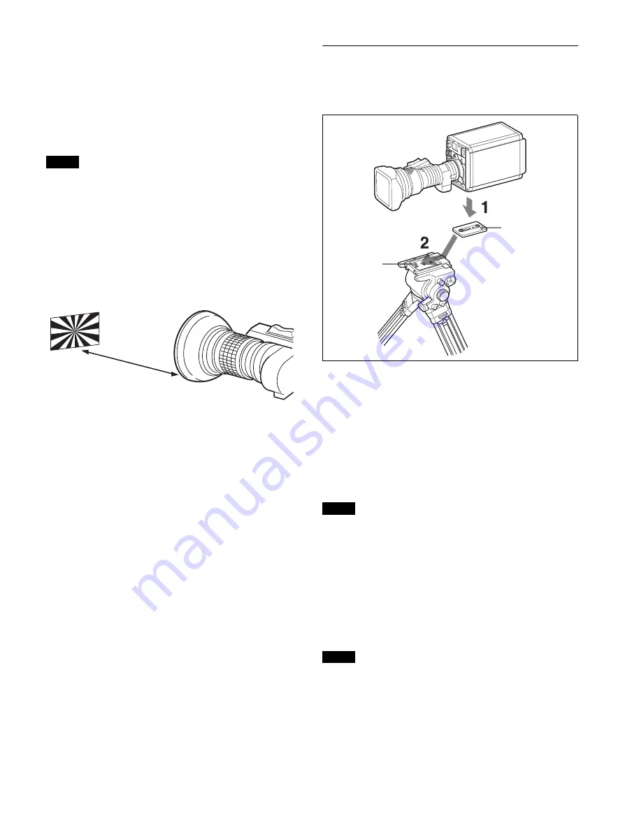
1

Attach the camera mounting plate directly to the 
camera.
(Two 3/8-inch tripod screws: screw depth of 10 mm 
(13/32 inches) or less)

2

Place the camera on the tripod and mount the camera 
by sliding it forward along the groove of the tripod 
plate until it clicks into place.

3

Make sure that the camera is securely attached by 
moving it back and forth.

If the screws of the camera mounting plate are 1/4-inch tripod 
screws, use inch conversion screws (Sony Part No.: 
4-170-419-02) to attach the plate. For details on purchasing 
inch conversion screws, and other information, contact a Sony 
service representative or Sony sales representative.

When using V shoe and VCT-14 tripod 
attachment

Use an optional V shoe (Sony Part No.: A-8279-993-D) and 
VCT-14 tripod attachment to mount the camera to the tripod.

• Select an appropriate hole from among those at the bottom 

of the tripod attachment, taking into consideration the 
balance of the weight of the camera and the tripod 
attachment. If an inappropriate hole is selected, the center 
of gravity may be off center, which may cause the camera to 
fall over and may cause an injury.

• Check that the size of the selected hole matches that of the 

screw of the tripod. If they do not match, the tripod 

Note

About 3 meters (10 ft)

Note

Notes

Camera mounting 
plate

Tripod plate

Summary of Contents for HDC-P43

Page 1: ...MULTI PURPOSE CAMERA HDC P43 OPERATION MANUAL English 1st Edition Revised 1 ...

Page 2: ... Camera Input Outputs 12 Setting the Focus Assist Functions 12 Monitor Screen Status Display 15 Menu Operations 16 Starting Menu Operations 16 Selecting Pages 17 Setting Menu Items 18 Editing the USER Menu 19 Menu List 22 Menu Tree 22 OPERATION Menu 27 PAINT Menu 32 MAINTENANCE Menu 38 FILE Menu 41 DIAGNOSIS Menu 44 Appendix 45 Precautions 45 Error Messages 45 Using a USB Drive 46 Specifications 4...

Page 3: ...oting It provides accurate color conversion even when shooting under conditions that would otherwise exceed the color conversion range of traditional matrix functions such as under strong monochromatic blue light sources Multimatrix color correction In addition to the standard 6 axis matrix function the unit has a multimatrix function that permits you to adjust the hue and chroma independently for...

Page 4: ...arker on a monitor Also there are indicators along the top and bottom of the monitor such as a tally lamp battery warning indicator and an indicator that warns you when one or more settings are not within standard range Menu based operation function You can make selections and settings related to monitor display items safety zone marker center marker and screen size marker etc quickly and easily w...

Page 5: ...nce with a single mode fiber cable ST connector and optical fiber cable is approximately 5 km max b The SZC 4002 4002M 4002W HFR software option must be installed for HFR High Frame Rate imaging at 4 6 8 speeds V shoe Dual HD SDI video outputs Single mode fiber cable ST connector 1 pair HKCU SM100 CCU Extension Adapter a Optical fiber cable HDCU4300 Camera Control Unit b BNC MSU 1000 series Master...

Page 6: ...g at 4 6 8 speeds V shoe Dual HD SDI video outputs Single mode fiber cable ST connector 1 pair HKCU SM100 CCU Extension Adapter a Optical fiber cable HDCU2000 Camera Control Unit BNC HDCU2500 Camera Control Unit MSU 1000 series Master Setup Unit RCP 1000 series Remote Control Panel BNC Video monitor Waveform monitor Video router CCA 5 LAN cable Optical fiber cable Hub RCP 1000 series Remote Contro...

Page 7: ...roximately 5 km max b The SZC 4002 4002M 4002W HFR software option must be installed for HFR High Frame Rate imaging at 4 6 8 speeds V shoe Dual HD SDI video outputs Single mode fiber cable ST connector 1 pair HKCU SM100 CCU Extension Adapter a Optical fiber cable HDCE 100 Camera Extension Adapter Optical fiber cable BPU4000 BasebandProcessor Unit b 2K video monitor 4K video monitor RCP 1000 serie...

Page 8: ...tor The rear tally lamp also serves as a battery alarm function If the voltage of the XLR input connected to the camera decreases the rear tally lamp flashes If the voltage approaches the limit the rear tally lamp switches to high speed flashing The alarm voltage for starting flashing can be set in the BEFORE END item of the BATTERY ALARM page of the MAINTENANCE menu and the alarm voltage for swit...

Page 9: ... CCU s NETWORK TRUNK connector to the network l SDI 1 serial digital interface connector and SDI 2 connector BNC type The SDI 1 connector outputs the display selected using the DISPLAY MENU switch as an HD SDI signal Various output signals can also be selected in the menu The SDI 2 connector outputs various output signals that can be selected in the menu as a 3G SDI signal or HD SDI signal and can...

Page 10: ...ew Mounting the Camera to a Tripod When using the supplied camera mounting plate 1 Attach the camera mounting plate directly to the camera Two 3 8 inch tripod screws screw depth of 10 mm 13 32 inches or less 2 Place the camera on the tripod and mount the camera by sliding it forward along the groove of the tripod plate until it clicks into place 3 Make sure that the camera is securely attached by ...

Page 11: ...he tripod attachment and mount the camera by sliding it forward along the groove of the tripod attachment until it clicks into place 4 Make sure that the camera is securely attached by moving it back and forth To remove the camera from the tripod attachment Hold down the red button and pull the lever in the direction of the arrow If the pin of the tripod attachment does not return to its original ...

Page 12: ...ectors of the camera you can output the HD prompter signal that is input to the camera control unit The HD prompter function can only be used when a single format is selected and the network TRUNK function is set to OFF a When the output from the SDI 1 connector is set to HD PROMPTER the output image may not be displayed correctly if a camera HD prompter signal whose format does not match the came...

Page 13: ...components of the video signal only for video signals on a viewfinder 7 Turn the MENU SEL knob ENTER button to display the desired setting and press the MENU SEL knob ENTER button 8 To finish the adjustment set the DISPLAY MENU switch to OFF to exit Menu mode Displaying the focus assist indicators The focus assist indicator function extracts the irregularities of a subject and converts the integra...

Page 14: ...h has been precisely adjusted For details about the flange focal length see Adjusting the Flange Focal Length page 9 Displaying the focus position meter The focus position meter function allows you to graphically display the registered focus position marker and the current focus position index graphically on the viewfinder screen You can set the focus to the registered point easily by adjusting th...

Page 15: ... MENU SEL knob ENTER button 5 To finish the adjustment set the DISPLAY switch to OFF to exit Menu mode Monitor Screen Status Display Besides the video image a monitor connected to the SDI 1 connector VF setting can display text and messages showing the camera settings and operation status as well as items such as a center marker or safety zone marker When the DISPLAY MENU switch is set to DISPLAY ...

Page 16: ...U Light sensor level at the CAMERA connector of the CCU If a camera control unit other than an HDCU2000 2500 or HDCU4300 is connected correct indications may not be obtained Menu Operations The menu displayed on a monitor connected to the SDI 1 connector enable various settings of the camera to be configured The following controls are used to operate the menus Turn the MENU SEL knob ENTER button o...

Page 17: ...nfirm the self diagnostic information To select a menu on the TOP MENU screen 1 Turn the MENU SEL knob ENTER button to align the arrow marker with the desired menu indication 2 Press the MENU SEL knob ENTER button The CONTENTS page or the last operated page of the selected menu is displayed Selecting Pages When selecting a page from a CONTENTS page Example CONTENTS page of the OPERATION menu Turn ...

Page 18: ...r can be moved by rotating the MENU SEL knob ENTER button 1 Set the cursor to the position where you wish to enter a character then press the MENU SEL knob ENTER button Another cursor appears on the character list 2 Set the cursor to the character to be entered and press the MENU SEL knob ENTER button Repeat steps 1 and 2 By selecting INS on the line below the character list you can enter a space ...

Page 19: ...ed appears 3 If the CONTENTS page is displayed turn the MENU SEL knob ENTER button to move the arrow marker to any of USER 1 EDIT to USER 19 EDIT then press the MENU SEL knob ENTER button to display the page If a different page is displayed turn the MENU SEL knob ENTER button until the desired page appears then press the MENU SEL knob ENTER button to select the page Example When you select the USE...

Page 20: ...ENU SEL knob ENTER button to move the arrow marker to the item above which you wish to insert a blank line The EDIT FUNCTION screen appears 2 Select BLANK then press the MENU SEL knob ENTER button The previously displayed page appears again and a blank line is inserted above the specified item You cannot insert a blank line on a page where 10 items have already been registered Editing by pages You...

Page 21: ...S and press the MENU SEL knob ENTER button To move a page Proceed as follows 1 Display the EDIT PAGE screen of the USER MENU CUSTOMIZE menu Turn the MENU SEL knob ENTER button to move the arrow marker to the page that you wish to move The EDIT FUNCTION screen appears 2 Select MOVE then press the MENU SEL knob ENTER button The EDIT PAGE screen appears again 3 Turn MENU SEL knob ENTER button to move...

Page 22: ... LIMIT FAR LIMIT DIRECTION SIZE RULED LINE INDEX COLOR INDEX WIDTH MARKER WIDTH CURRENT FOCUS DIST EX ZOOM DISP FOCUS ND CC 5600K IRIS GAIN SHUTTER BATT RETURN MESS FOLLOW F FOCUS NAME FOCUS FORM AGE MARKER LEVEL CENTER SAFETY ZONE EFFECT ASPECT MASK SAFETY VF DETAIL CRISP FREQUENCY FLICKER AREA ZOOM LINK COLOR DE RETURN DISABLE TAIL PEAK COLOR CHROMA LEVEL CURSOR 08 U06 CURSOR BOX CURSOR FILE 09 ...

Page 23: ...US P01 VIDEO LEVEL P02 COLOR TEMP P03 GAMMA P04 BLACK GAMMA P05 SATURATION P06 KNEE P07 WHITE CLIP P08 DETAIL 1 P09 FLARE GAMMA BLK GAM KNEE WHT CLIP DETAIL LVL DEP SKIN DTL MATRIX WHITE BLACK FLARE GAMMA V MOD FLARE V MOD TEST WHITE AUTO WHITE ATW SPEED BALANCE COLOR TEMP BALANCE MASTER LEVEL COARSE TABLE GAMMA TEST LEVEL RANGE TEST SATURATION LOW KEY SAT RANGE TEST K POINT K SLOPE KNEE KNEE MAX ...

Page 24: ...ER MULTI ADAPTIVE MATRIX PHASE HUE SAT ALL CLEAR GATE MATRIX PRESET USER MULTI SHUTTER ECS FREQ 4K DETAIL DETAIL P12 LEVEL LIMITER M LIMITER WHT LIMITER BLK CRISP LEVEL DEPEND H V RATIO FREQ MIX RATIO KNEE APT ABS DISSOLVE NOISE SUPPRESSION P17 SCENE FILE P21 SPEED FLICKER REDUCTION P18 P HDR OPERATION P19 OWER LINE FREQUENCY REDUCTION MODE LIGHT TYPE GAIN OFFSET LIMITER ACM TYPE HDR MODE SDR GAIN...

Page 25: ...L RATIO IRIS GAIN IRIS CLOSE F N AF DISPLAY O DISP ALAC F DROP COMP MAX GAIN DROP POINT ROUNDNESS STORE LENS FILE REMOTE CONTROL CONTROL MODE FOLLOW FOCUS OFFSET ADJUST SENS OFFSET CANCEL GAIN MIC CCU CALL CAM CALL FRONT TALLY BRIGHTNESS 48V MUTE REAR TALLY SYSTEM FORMAT M10 U09 CHANGE CURRENT SDI OUT M11 U10 TRUNK M12 SDI 1 OUT SDI 2 OUT IN EMB AUDIO TRUNK INTERFACE NETWORK TRUNK LINK OTHERS M16 ...

Page 26: ... CAM PRESET FILE ID CAM CODE DATE STORE FILE No NAME F NO CENTER MARKER H POS V POS STORE STORE FILE MATRIX FILE F07 STORE FILE 1 2 3 4 5 CLEAR ALL READ USB t CAM WRITE CAM t USB FILE ID CAM CODE DATE CUSTOM PRESET MATRIX FILE CLEAR F09 PRESET OPERATOR REFERENCE ALL 10 SEC CLEAR OHB WHITE SHADE ALL OHB BLACK SHADE OHB ND OFFSET BOX CURSOR FILE F08 1 2 4 STORE READ USB t CAM WRITE CAM t USB 5 3 EFF...

Page 27: ...he FOCUS display format NORMAL Displayed in the range 0 to 255 no units ABS AUTO Displayed in the units meters or feet set on the lens ABS m Displayed in meters ABS ft Displayed in feet VF MARKER 02 U05 MARKER ON OFF Sets MARKER to ON OFF WHITE BLACK DOT LEVEL 0 to 100 40 CENTER ON OFF 1 2 3 4 1 Full cross 2 Full cross with a hole 3 Center 4 Center with a hole SAFETY ZONE ON OFF 80 0 90 0 92 5 95 ...

Page 28: ...IMIT 0 to 999 Sets the FAR edge of the focus position meter DIRECTION HORIZONTAL VERTICAL Sets the display direction of the focus position meter HORIZONTAL Horizontal display at the top of the screen VERTICAL Vertical display along the right edge of the screen SIZE NORMAL HALF Sets the display size of the focus position meter RULED LINE OFF ON Shows hides ruled lines INDEX COLOR BLACK WHITE Sets t...

Page 29: ...olor of triangular parts of the marker Cannot be registered here if marker registration has been assigned to a dedicated switch NAME MKR1 2 3 Max 8 characters Default value MARKER 1 to 3 Sets the text of the marker name See To specify a character string page 18 POS MKR1 2 3 0 to 999 Sets the position of the marker CURRENT FOCUS DIST Displays the current focus distance display only FOCUS ASSIST 06 ...

Page 30: ...3 4 5 STORE Stores a BOX CURSOR FILE name in the camera READ USB t CAM Transfers BOX CURSOR FILE from a USB drive to the camera WRITE CAM t USB Transfers BOX CURSOR FILE from the camera to a USB drive SPIRIT LEVEL 10 INDICATOR ON OFF When this is set to ON BOX MEMORY for CURSOR does not function MODE 1 2 Switches the display method of the indicator REVERSE OFF ON Inverts the movement of the indica...

Page 31: ... MODE PinP OFF PinP RETURN 1 2 3 4 PinP HD PROMPTER 1 2 Main picture Return picture HD Prompter picture Cannot be used during standalone operation OPERATION Page name Page No Item Settings Description PinP OFF PinP RETURN PinP HD PROMPTER Mode RET SW OFF RET SW ON Mode RET SW OFF RET SW ON 1 2 3 4 Mode RET SW OFF RET SW ON 1 2 ...

Page 32: ...RETURN1 SW RETURN2 SW RETURN3 SW VF DETAIL SPIRIT LEVEL INDICATOR FOCUS ASSIST INDICATOR PinP VTR S S TALLY R TALLY G CALL OPERATOR FILE 13 READ USB t CAM Execute using ENTER Reads the operator file from a USB drive WRITE CAM t USB Execute using ENTER Writes the current settings of the operator file items to a USB drive PRESET Execute using ENTER Sets the operator file items to the preset values i...

Page 33: ...n be independently set COARSE 0 35 to 0 90 0 05 steps 0 45 TABLE STANDARD HYPER USER 1 2 3 4 5 6 7 With STANDARD or USER selected only 1 to 5 are available for USER 1 Equivalent to a camcorder 2 4 5 gain 3 3 5 gain 4 Equivalent to SMPTE 240M 5 Equivalent to ITU R709 6 5 0 gain 7 5 0 709 1 2 3 4 With HYPER selected 1 325 to 100 2 460 to 100 3 325 to 109 4 460 to 109 GAMMA ON OFF TEST OFF SAW 10STEP...

Page 34: ... value is displayed in ABS mode ON OFF ABS Highlighted ABS Absolute mode DETAIL 2 P10 H V RATIO 99 to 99 0 Absolute value is displayed in ABS mode FREQ 99 to 99 0 Absolute value is displayed in ABS mode MIX RATIO 99 to 99 0 Absolute value is displayed in ABS mode KNEE APT 99 to 99 0 Absolute value is displayed in ABS mode ON OFF DTL H V MODE H V V only ABS Highlighted ABS Absolute mode HD DETAIL P...

Page 35: ...OFF 1 2 3 MAT 1 2 3 The skin gate function can be turned on for the specified channel only MAT Displayed when GATE of MULTI MATRIX is ON ABS Highlighted ABS Absolute mode NATURAL SKINDTL OFF ON ZOOM LINK OFF ON TELE 0 to 99 WIDE 0 to 99 CH SW 1 ON 2 3 ON OFF Sets the skin tone detail function independently for each channel Channel 1 is always set to ON Absolute values are indicated for LEVEL only ...

Page 36: ...5 USER ON OFF MULTI ON OFF SHUTTER P16 SHUTTER ON OFF ON OFF Settings in When a remote control unit panel or a CCU is not connected cannot be changed 29 97P 1 40 1 60 1 100 1 120 1 125 1 250 1 500 1 1000 1 2000 ECS 25P 1 33 1 50 1 100 1 125 1 250 1 500 1 1000 1 2000 ECS 24P 23 98P 1 32 1 48 1 96 1 100 1 125 1 250 1 500 1 1000 1 2000 ECS 59 94P 1 100 1 125 1 250 1 500 1 1000 1 2000 ECS 50P 1 60 1 1...

Page 37: ...ection limiter on off ACM TYPE 1 2 3 4 Enabled only when ACM is selected Selects the combination of frames to add More frames are added as the value increases HDR OPERATION P19 HDR MODE OFF LIVE HDR CINEMA Displays the BPU setting SDR GAIN 0 0 to 15 dB Enabled only when LIVE HDR is selected Gain setting applied to the SDR output HDR CONTRAST 100 to 560 Enabled only when LIVE HDR is selected HDR ou...

Page 38: ...ne files seamlessly SPEED 0 2 to 2 8 0 2 steps 3 to 10 1 steps 0 2 MAINTENANCE Page name Page No Item Settings Description AUTO SETUP M01 AUTO BLACK Execute using ENTER AUTO WHITE Execute using ENTER AUTO LEVEL Execute using ENTER AUTO WHITE SHADING Execute using ENTER TEST OFF SAW 10STEP WHITE SHADING M02 V SAW R G B 99 to 99 0 R G and B values can be independently set V PARA R G B 99 to 99 0 H S...

Page 39: ...isplays the value returned from the lens When AUTO IRIS is on the value returned from the lens is always displayed AF DISPLAY ON OFF OFF EFFECT OFF ASSIST IND OFF EFFECT Displayed when EFFECT of VF MARKER is ON OFF ASSIST IND Displayed when INDICATOR of FOCUS ASSIST is ON ALAC AUTO OFF With AUTO selected the status is displayed at the right ACTIVE Compensation is in progress WAIT Waiting for compl...

Page 40: ...e offset of the MSU OFFSET CANCEL GAIN 1 2 3 4 5 Sets the sensitivity of canceling the offset on the demand side MIC GAIN M08 MIC 20 30 40 50 60 dB Enabled in standalone mode 48V ON OFF MUTE ON OFF CALL TALLY M09 CCU CALL OFF ON CAM CALL OFF ON FRONT TALLY OFF ON BRIGHTNESS 0 to 100 50 REAR TALLY OFF ON SYSTEM FORMAT M10 U09 CURRENT 1080 50P 2 50P 3 50P 4 50P 6 50P 8 59 94P 2 59 94P 3 59 94P 4 59 ...

Page 41: ...ion AUTO2 Slow rotation CAM BARS ON OFF Enabled in standalone mode WHITE SETUP MODE AWB A LVL OPTION KEY M17 READ USB t CAM Execute using ENTER Reads the install key from a USB drive EFFECTIVE FUNCTION Displays only installed items MAINTENANCE Page name Page No Item Settings Description FILE Page name Page No Item Settings Description OPERATOR FILE F01 READ USB t CAM Execute using ENTER Reads the ...

Page 42: ...items in the reference file in internal memory STANDARD Execute using ENTER Reads the standard values in the reference file in internal memory ALL PRESET Execute using ENTER Resumes the factory preset reference file READ USB t CAM Execute using ENTER Loads a reference file from a USB drive WRITE CAM t USB Execute using ENTER Writes the current settings of the reference file items as a reference fi...

Page 43: ...X to CUSTOM 1 to 5 STORE FILE 1 Execute using ENTER 2 Execute using ENTER 3 Execute using ENTER 4 Execute using ENTER 5 Execute using ENTER CLEAR ALL Execute using ENTER Clears all the files READ USB t CAM Execute using ENTER Loads five preset files from a USB drive to internal memory WRITE CAM t USB Execute using ENTER Writes five preset files in the camera s memory to a USB drive FILE ID Max 14 ...

Page 44: ... ENTER DIAGNOSIS Page name Page No Item Indication Description OPTICAL LEVEL D01 CCU t BPU t CAM GREEN YELLOW RED NG NO SIGNAL Displayed only when a CCU or BPU is connected CAM t BPU t CCU GREEN YELLOW RED NG NO SIGNAL Displayed only when a CCU or BPU is connected CABLE LENGTH x x km Displays the camera cable length Displayed only when a CCU is connected BOARD STATUS D02 OHB OK NG DPR OK NG SY OK ...

Page 45: ...normal usage 8 hours per day 25 days per month If usage exceeds the above normal usage frequency the life expectancy may be reduced correspondingly Camera CMOS image sensor phenomena The following phenomena that may occur in images are specific to image sensors They do not indicate a malfunction White flecks Although the image sensors are produced with high precision technologies fine white flecks...

Page 46: ...K NG A problem is detected in the optical block MSU RPN BUSY RPN compensation was attempted using the camera menu while being operated from an external device Consult Sony service personnel VF RPN BUSY RPN compensation was attempted from an external device while being operated using the camera menu Consult Sony service personnel NO USB FLASH DRIVE A USB drive operation was attempted with no USB dr...

Page 47: ... 17 V DC SDI 1 SDI 2 BNC type 1 each PROMPTER OUT BNC type 1 1 Vp p 75 ohm EXT I O D sub 15 pin female 1 USB USB 2 0 Type A 4 pin 1 for connecting USB drive NETWORK TRUNK RJ 45 type 8 pin 1 Supplied accessories Operation guide 1 set Operation manual CD ROM 1 Camera number label 1 Optional Accessories Tripod Attachment VCT 14 4K Upgrade Software SZC 4001 4001M 4001W Related Equipment BPU4000 4500 B...

Page 48: ...A 4 RX0 for RS 422A RX0 for RS 232C IN TRUNK Data IN 5 RX0 for RS 422A RX1 for RS 232C IN TRUNK Data IN 6 ASSIGN1 IN IN Contact Low Active GND 7 GND 8 MIC X IN 60 to 20 dBu Balanced 9 R TALLY OUT Open Collector max 10 mA 10 GND 11 TX0 for RS 422A TX0 for RS 232C OUT TRUNK Data OUT 12 TX0 for RS 422A TX1 for RS 232C OUT TRUNK Data OUT 13 ASSIGN2 IN IN Contact Low Active GND 14 MIC GND 15 MIC Y IN 6...

Page 49: ...HDC P43 JN SY CE CN 4 691 430 12 1 2016 Sony Corporation ...

Reviews: