background image

HBD-N590/N790W/N890W/N990W/N995W/T79

HBD-N590/N790W/N890W/N990W/N995W/T79

50

50

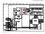
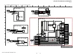
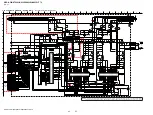
5-13.  SCHEMATIC  DIAGRAM - MB-149 Board (8/11) -

• See page 71 for IC Pin Function Description.

Note: 

IC101 on the MB-149 board cannot exchange with single. When 
this part is damaged, exchange the complete mounted board.

3.3

3.3

3.2

3.3

3.2

IF_SCK

JL1014

GND

JL1028

JL1017

JL1001

USB_PCONT1

JL1016

JL1019

JL1024

JL1026

JL1006

OPWRSB

JL1020

JL1011

IF_SDI

0

R1023

JL1007

10k

RB1002

R1012

10k

JL1010

R1016

10k

JL1023

JL1004

R1028

10k

JL1018

JL1015

JL1021

JL1003

JL1022

R1010

10k

CPU_XRST

JL1009

10k

R1014

R1002

10k

JL1013

R1022

0

10k

RB1001

10k

R1008

UPG_STATUS

JL1005

JL1002

START_BIT

IF_SDO

USB_PCONT2

SYS_REQ

STRAP_AOSDATA0

STRAP_AOSDATA1

STRAP_AOSDATA2

STRAP_AOLRCK

XIF_CS

JL1029

JL1030

JL1031

JL1032

JL1034

JL1033

JL1036

JL1037

JL1038

JL1039

JL1040

JL1041

JL1042

JL1043

JL1044

JL1045

JL1046

JL1047

R1044

10k

EXT_RXD

EXT_TXD

EXT_JIG_MODE1

EXT_JIG_MODE0

R1027

10k

R1018

100

R1019

100

R1020

100

R1021 100

AMUTE

G4

VSTB

AH27

VDATA

AG27

VCLK

AG26

LCDRD

AG28

GPIO0

E4

GPIO1

D1

GPIO2

E2

GPIO3

E1

GPIO4

G1

GPIO5

H2

GPIO6

E3

GPIO7

F3

GPIO8

AG25

GPIO9

H3

GPIO10

C4

GPIO11

C5

GPIO12

A2

GPIO13

C3

GPIO14

A1

GPIO15

C1

GPIO16

D2

GPIO17

D3

GPIO18

D4

GPIO19

F5

GPIO20

G5

GPIO21

F4

GPIO22

G3

GPIO23

G2

GPIO24

B2

GPIO25

B1

GPIO26

C2

GPIO27

AC24

SCL

B3

SDA

A3

UATXD

AH26

UARXD

AF25

RESET_

AF26

EFPWRQ

H1

IR

AH28

OPWRSB

AH25

VOUTVSYNC

L25

VOUTHSYNC

L24

VOUTCLK

P22

VOUTD0

W26

VOUTD1

W25

VOUTD2

V23

VOUTD3

R24

VOUTD4

V24

VOUTD5

V25

VOUTD6

U25

VOUTD7

U24

VOUTD8

R23

VOUTD9

U23

VOUTD10

T26

VOUTD11

U26

VOUTD12

P24

VOUTD13

P25

VOUTD14

P23

VOUTD15

P26

R1410

4.7k

75

R1401

0

R1402

C1410

0.1

R1411

4.7k

1

2

3

4

5

6

7

8

9

10

11

12

13

14

15

16

17

18

19

20

MFI341S2164

IC1402

NC

MODE1

NC

RESET

VCC

NC

NC

NC

NC

NC

VSS

I2C_SCL

I2C_SDA

MODE0

NC

NC

NC

NC

NC

NC

47p

C1406

0

R1405

3.3V

JL1403

R1403

0

J1401

R1413

0

VDACX_OUT

U27

VDACG_OUT

V28

VDACB_OUT

U28

VDACR_OUT

W27

AVDD33_VDAC_X

V22

AVSS33_VDAC_X

U22

AVDD33_VDAC_BG

T27

AVSS33_VDAC_BG

T22

0.1

C1402

47p

C1407

10

C1401

1.8uH

L1401

JL1402

JL1404

JL1401

C1408

1000p

(8/11)

MB-149 BOARD

(12/15)

CSP

IC101

(Chip Size Package)

BD DECODER

(13/15)

CSP

IC101

(Chip Size Package)

BD DECODER

(14/15)

CSP

IC101

(Chip Size Package)

BD DECODER

EEPROM

IC1402

VIDEO OUT

CXD90011G-BC (EXCEPT SP, TW, TH, CH)

CXD90011G-BB (SP, TW, TH, CH)

IC101

CXD90011G-BC (EXCEPT SP, TW, TH, CH)

CXD90011G-BB (SP, TW, TH, CH)

IC101

CXD90011G-BC (EXCEPT SP, TW, TH, CH)

CXD90011G-BB (SP, TW, TH, CH)

IC101

(CHASSIS)

MB-149

(11/11)

BOARD

>116S

BOARD

>114S

MB-149

(7/11)

BOARD

>107S

MB-149

(5/11)

BOARD

>117S

MB-149

(3/11)

8

I

2

A

D

5

K

B

7

C

6

11

3

H

F

G

9

E

10

1

J

4

(EXCEPT RU, E12)

(Page 53)

(Page 49)

(Page 47)

(Page 45)

Ver. 1.1

Summary of Contents for HBD-N590

Page 1: ...nt R Surround L Surround R 125 W per channel at 3 ohms 1 kHz Center 250 W at 6 ohms 1 kHz Subwoofer 250 W at 6 ohms 80 Hz Inputs Analog AUDIO AUDIO IN Sensitivity 3 0 V 1 0 V Inputs Digital TV Audio Return Channel OPTICAL Supported formats LPCM 2CH up to 48 kHz Dolby Digital DTS HDMI IN 1 HDMI IN 2 Supported formats LPCM 5 1CH up to 48 kHz LPCM 2CH up to 96 kHz Dolby Digital DTS Video Section Outp...

Page 2: ...rights reserved by Verance Reverse engineering or disassembly is prohibited iPhone iPod iPod classic iPod nano and iPod touch are trademarks of Apple Inc registered in the U S and other countries Made for iPod and Made for iPhone mean that an electronic accessory has been designed to connect specifically to iPod or iPhone respectively and has been certified by the developer to meet Apple performan...

Page 3: ...c Diagram MB 149 Board 2 11 44 5 8 Schematic Diagram MB 149 Board 3 11 45 5 9 Schematic Diagram MB 149 Board 4 11 46 5 10 Schematic Diagram MB 149 Board 5 11 47 5 11 Schematic Diagram MB 149 Board 6 11 48 5 12 Schematic Diagram MB 149 Board 7 11 49 5 13 Schematic Diagram MB 149 Board 8 11 50 5 14 Schematic Diagram MB 149 Board 9 11 51 5 15 Schematic Diagram MB 149 Board 10 11 52 5 16 Schematic Dia...

Page 4: ... 506 Single Layer PAL J 6090 078 A HLX 507 Dual Layer PAL TEST DISC Note Refer to the service manual of BDP BX1 S350 Part No 9 883 989 1 page 1 3 to 1 14E for the use of BLX 104 204 Operation and Display 1 BLX 104 Procedure 1 Select 23 976Hz 1080p 2 Play 4 Motion picture 3 Check whether player can play back or not 4 Check each outputs Video Composite HDMI Audio Speaker out When 1080 24p monitor is...

Page 5: ... 1 3 Barcode decoder BDPRdec 1 3 Barcode decoder BDPRdec Jig name BDPRdec exe Software contents BDPRdec exe Barcode decoder software SavePath ini Decoded file destination setting file Ini tial destination is C BuData txt TasmanBars dll Decode dll Uninst exe Uninstall the BDPRdec exe from PC Note When working by OS of the version after VISTA it is necessary to change destination of the decoded file...

Page 6: ...e MB 149 board and replace it when it has been damaged Confirm whether the optical device IOP is normal in the service mode Refer to 2 2 Flow of optical device IOP check Repalece the optical device KEM 480AAA Refer to 3 Optical device KEM 480AAA replacement NO YES OK YES YES NO NO Note Refer to 2 19 BOTTOM COVER page 24 about how to remove the BOTTOM COVER 2 2 Flow of optical device IOP check YES ...

Page 7: ...his unit 4 Drag drop the taken photo by step 2 to BDPRDec exe and make the text data File name BuData txt 5 Save the text data to USB memory 6 Connect USB memory with side USB connector on this unit and turn the power on Rear view 7 Press the FUNCTION button on the remote commander to select BD DVD 8 Press the buttons on the remote commander in order of DISPLAY 0 2 1 SUBTITLE and enter the service...

Page 8: ... 417 422 0 HBD N890W TW 4 417 424 0 HBD N990W E12 4 417 425 0 HBD N990W E3 4 417 426 0 HBD N990W E15 4 417 427 0 HBD N990W SP 4 417 428 0 HBD N990W AUS 4 417 429 0 HBD N990W TH 4 417 430 0 HBD N990W TW 4 417 431 0 HBD N790W PX 4 422 025 0 HBD N890W RU 4 429 510 0 NOTE OF REPLACING THE IC3102 AND IC3302 ON THE NX_AMP BOARD AND THE COMPLETE NX_AMP BOARD When IC3102 and IC3302 on the NX_AMP board and...

Page 9: ...ult 7 Press the 1 button to turn the power off Note Refer to the instruction manual about details of the setting method 2 Checking method of wired LAN operation Check that access point is recognized surely Procedure 1 Connect the main unit to the router or the hub etc with the LAN cable 2 Press the HOME button on the remote commander to enter the home menu 3 Press the m M buttons on the remote com...

Page 10: ...iver EZW RT50 HBD N790W N890W N990W T79 or EZW RT20 HBD N995W EZW RT50 Rear panel of the main unit HBD N790W N890W N990W N995W T79 Rear panel of the surround amplifier TA SA300WR 2 Connect the AC power cord of the main unit HBD N790W N890W N990W N995W T79 3 Press the 1 button on the main unit HBD N790W N890W N990W N995W T79 4 Connect the AC power cord of the surround amplifier TA SA300WR 5 When a ...

Page 11: ...ITCH TURN OFF NX_AMP BOARD SERVICE POSITION The BD drive is taken out and please rotate the pulley in the direction of the arrow by screwdriver etc after detaching and take out the disc disc BD drive bottom view insulating sheet NX_AMP board switching regulator SWR1 power cord ...

Page 12: ...7 LED BOARD Page 17 2 11 WS BOARD BLOCK EXCEPT N590 Page 19 2 12 SHIELD PS BLOCK Page 19 2 20 OPTICAL PICK UP KEM 480AAA Page 25 2 19 BOTTOM COVER Page 24 2 14 BRACKET PS Page 21 2 15 POWER CORD AC1 Page 21 2 16 HEAT SINK AMP Page 22 2 17 NX_AMP BOARD Page 22 2 8 WIRELESS LAN CARD WLC1 EXCEPT N995W Page 17 2 9 CHASSIS MIDDLE BLOCK Page 18 2 10 BRACKET DRIVE Page 18 2 18 MB 149 BOARD Page 23 2 21 H...

Page 13: ...top block 2 four claws Note 3 Align this portion into the groove and align screw boss beneath the screw hole Note 2 Since the wire flat type 11core is connected remove slowly screw hole screw boss groove Rear bottom view Rear top view Rear view Note 3 Align this portion into the groove and align screw boss beneath the screw hole screw hole screw boss groove Rear view Note 4 When installing the wir...

Page 14: ...or touch assy Bottom view reflector touch assy TOUCH board PWR_KEY board iUe VettiQJ 4 TOUCH board Note 3 Since it is pasted by adhesion sheet remove carefully Note 2 Please spread a sheet under a unit not to injure cover top Note 1 When TOUCH board is defective exchange the complete mounted board ...

Page 15: ...chassis main block in the direction of an arrow 1 Slant to fit the cord bushing underneath the claw of cover bottom block 2 Align two holes to two bosses and rest down at cover bottom block two bosses two holes cord bushing cover bottom block 4 chassis main block 5 cover bottom block 2 Open the lid USB side 2 Open the lid USB front N590 N790W N890W T79 N990W N995W RZ WR LQVWDOO WKH FRYHU ERWWRP EO...

Page 16: ...01 5 wire flat type 7 core CN1701 4 wire flat type 9 core CN1260 1 two screws BV3 1 two screws BV3 6 three screws BV3 7 bracket slot 8 sound sheet 9 BD drive BSX 3 2 Remove the BD drive block in the direction of an arrow Note When installing the wire flat type ensure the coloured line No slanting after insertion wire flat type coloured line connector ...

Page 17: ...LED board 3 cover indicator block 4 Remove the LED board in the direction of an arrow Note When the wireless LAN card WLC1 is replaced refer to CHECKING METHOD OF NETWORK OPERATION on servicing notes page 9 1 screw BV3 2 claw 3 Remove the wireless LAN card WLC1 in the direction of an arrow 5 wireless LAN card WLC1 4 connector Ver 1 1 ...

Page 18: ...V3 5 two screws BV3 6 chassis middle block 1 tape 2 wire flat type 11 core CN6303 3 wire flat type 15 core CN6304 Note When installing the wire flat type ensure the coloured line No slanting after insertion wire flat type coloured line connector 3 bracket drive 1 two screws BV3 2 three screws BV3 bracket drive LUH VHWWLQJ ...

Page 19: ...2 12 SHIELD PS BLOCK 3 WS board block 2 two screws BV3 1 wire flat type 13 core CN5909 Note When installing the wire flat type ensure the coloured line No slanting after insertion wire flat type coloured line connector 2 shield PS block 1 four screws BV3 1 three screws BV3 ...

Page 20: ...hing regulator SWR1 switching regulator SWR1 power cord coil 5 two screws BV3 5 screw BV3 1 power cord connector CN1 2 connector CN101 3 connector CN4 4 connector CN301 SAFETY STANDARD Note Check that the C351 is bended to the position as specified in the drawing Switching regulator SWR1 setting ...

Page 21: ...e cord bushing FBS001 in the direction of an arrow 1 two claws SAFETY STANDARD FBS 001 claw Cord bushing FBS001 setting Note When installing the cord bushing FBS001 mind the direction of claw at type No mark and align into the hole and press in fully 2 14 BRACKET PS 1 two screws B3 3 two screws B3 4 screw B3 4 screw B3 5 bracket PS bracket PS 2 insulator bottom Wire VeWWiQJ 2 15 POWER CORD AC1 ...

Page 22: ...screw B3 3 screw B3 2 screw B3 4 clamp 5 NX_AMP board 1 wire flat type 22 core CN3504 EXCEPT N590 24 core CN3505 N590 N590 Note 2 When installing the wire flat type ensure the coloured line No slanting after insertion wire flat type coloured line connector Note 1 When the NX_AMP board is replaced spread the compound referring to NOTE OF REPLACING THE IC3102 AND IC3302 ON THE NX_AMP BOARD AND THE C...

Page 23: ... Wire VeWWiQJ MB 149 board MB 149 board USB board tape USB board N590 N790W N890W T79 N990W N995W A B C 9 Remove the MB 149 board in the direction of an arrow wire flat type Note 2 When installing the wire flat type ensure the coloured line No slanting after insertion Note 3 Arrange the wire connected with the wireless LAN card to make the outside of MB 149 board crawl Note 3 Arrange the wire conn...

Page 24: ...e FFC guide in the direction of an arrow 5 FFC guide Note 2 When installing the FFC guide unite the position of two holes of FFC guide with two bosses of bottom cover 8 bottom cover Note 3 When installing the bottom cover unite the position of two holes of bottom cover with two bosses of loading assy wire flat type Note 1 When installing the wire flat type ensure the coloured line No slanting afte...

Page 25: ... up KEM 480AAA 5 insulator 5 insulator 5 insulator 5 insulator 4 flexible flat cable 45P 3 wire flat type 9 core BD drive bottom view Note When installing the wire flat type ensure the coloured line No slanting after insertion wire flat type coloured line connector 2 Remove the optical pick up block in the direction of an arrow ...

Page 26: ... is contact side The lower side is contact side Mountain fold Valley fold 115 mm 115 mm The lower side is contact side The lower side is contact side The lower side is contact side 117 mm 30 mm 51 mm 72 mm 12 mm 12 mm 146 mm NX_AMP board CN3504 MAIN board CN5904 MAIN board CN6304 12 mm 12 mm 146 mm NX_AMP board CN3505 FL board CN903 The lower side is contact side The lower side is contact side The...

Page 27: ...cord of the main unit HBD N790W N890W N990W N995W T79 3 Press the 1 button on the main unit HBD N790W N890W N990W N995W T79 4 Connect the AC power cord of the surround amplifier TA SA300WR 5 When a wireless transceiving becomes effective the LINK STANDBY indicator of surround amplifier TA SA300WR lights to green Note 2 Refer to the operating instructions when the LINK STAND BY indicator of surroun...

Page 28: ...ote commander is pressed the display changes from destination information STR version in this order and returns to the model informa tion display Each time the VOL button on the remote commander is pressed the version and date are switched 5 In the state of step 3 press the FUNCTION button on the remote commander and K 0 is displayed on the fluorescent indicator tube K 0 value increases whenever a...

Page 29: ...rsion of software By using network upgrade method or Disc upgrade method After finish upgraded Service member can perform wireless checking as mention in wireless LAN checking pages Or Confirm wireless LAN connection from customer mode in case of Wireless connection successfully establish The wireless Lan network connection will be judge as OK Date 26 January 2011 Note The operation in this mode m...

Page 30: ...ize default setting Log Displays Error Log Error Log Displays error log Diag Network Network diagnosis for wired Ping Ifconfig View network status Confirm network connection HDD log Device Test Front US D C IFcon test Video Test Video output test udio Test udio output test udio Input Test Not used ireless L N Test Not used EMC Test Mode Not used Drive Write drive OP data and check drive HDD Mode N...

Page 31: ...Selects the device to test Executes the test M Returns to selection of test category RETURN Returns to selection of test category List of test categories Device Test Video Test Audio Test Audio Input Test not used Wireless LAN Test not used Mic Test not used HDMI Input Test not used Transcoder Test not used Diag Category Diag Category Device Test Device Front USB Media check OK Checking HELP RIGHT...

Page 32: ...ach log display screen with the USB memory device inserted into the unit Note Please do not press the RED button immediately after USB mem ory is inserted Please do not pull out USB memory immediately after the RED button was pressed Error Log When getErrLogFile trm fi le exists in the USB memory de vice errlog log fi le is output Select Log HELP DOWN ENT NUM Error Log 02 174 2010 01 01 00 00 08 E...

Page 33: ...icing 16 System Information System Information Display This screen displays system information Screen 1 Basic Information Operation Drive information delta IOP of a drive is measured and wireless device information displayed go to Screen 2 RETURN Returns to the top menu of the service mode Screen 2 Drive and Wireless Information Menu Operation Basic Information displayed go to Screen 1 RETURN Retu...

Page 34: ...ta Write 2 Servo Parameter Check Menu Not used 3 Servo Signal Check Menu Not used 4 S Curve Check Menu Not used 5 Readability Check Menu Not used 6 OP Position Check Menu Not used 7 OP Check Menu Not used 8 Load Eject Aging Not used 9 Spindle Control Check Menu Not used 10 FA Test Mode Not used Screen 2 To start OP data Write Displayed characters values in the following figure are example Operatio...

Page 35: ...14 NTSC HLX 506 507 PAL Procedure 1 After displayed Main Menu select 1 Video Signal 2 Play 1 Color bar 100 Check the picture and sound output 3 Return to Menu 4 Play Demonstration 4 3 or Demonstration 16 9 Check the picture and sound output 1 2 Playback operation confirmation Confirm operation in each signal output mode of test disc BLX 104 204 according to the content of the repair Note AV Sync d...

Page 36: ...B 98 MHz C 108 MHz Deviation 75 kHz Modulation 1 kHz ANT input 35 dBu EMF Note Please use 75 ohm coaxial cable to connect SG and the set You cannot use video cable for checking Please use SG whose output impedance is 75 ohm 3 Set to FM tuner function and scan the input FM signal with automatic scanning 4 Confirm that input Frequency of A B and C detected and auto matic scanning stops The stop of a...

Page 37: ...SA_A SA_A STP2_P 54 STP2_N 55 SA_B SA_B STP1_P 52 STP1_N 53 SCLK 15 SSZ 14 XRSTIN 19 TXVN_1 AC27 LAN 100 USB 1 USB_DP_P1 A4 USB_DM_P1 DP DM B4 USB 2 SIGNAL PATH CN760 HDMI IN 1 CN770 HDMI IN 2 P27 P28 7 9 4 6 1 3 10 DATA0 DATA0 DATA1 DATA1 DATA2 DATA2 CLOCK CLOCK SDA 5V SCL 5V 5V POWER HOT PLUG DET 18 CEC 13 12 16 15 AF27 AF28 7 9 4 6 1 3 10 DATA0 DATA0 DATA1 DATA1 DATA2 DATA2 CLOCK CLOCK SDA 5V S...

Page 38: ...A0 D1A14 NFWEN AE24 18 WE NFREN AE21 8 RE NFCEN NFRBN AF22 AD21 9 7 CE RY BY NFALE NFCLE AF24 AD22 17 16 ALE CLE EEPROM IC1402 SDA A3 13 I2C_SDA SCL B3 12 I2C_SCL 4 RESET 19 WP IO1 IO8 X401 27MHz NS_XTALO NS_XTALI C28 C27 CPU_XRST T2 RESET RRESET AD9 L3 L2 WE M2 BA0 N8 BA1 M3 BA2 CS K3 J3 CAS RAS K9 CKE J7 CK K7 CK D3 C7 DMU DQSU B7 E7 DQSU DML K1 ODT F3 DQSL G3 DQSL L3 L2 WE M2 BA0 N8 BA1 M3 BA2 ...

Page 39: ... USB_VBUS_PCONT2 PCONT_FL 25 PCONT_FL PCONT2 37 PCONT2 PCONT3 38 PCONT3 PVDD_CONT PVDD_CONT 47 PCONT1 PCONT1 36 FAN_CONT 2 FAN_CONT FAN_ON 42 FAN_ON IF_SDO 75 JIG_MODE1 82 IF_SDI 76 IF_SCK 77 XIF_CS UPG_STATUS OPWRSB BD_IF_START 19 BD_IF_REQ 23 78 85 83 S AIR_GPIO2 S AIR_DET WS_SDA 28 S AIR_RST WS_SCL 27 87 88 86 PCONT3 8 CLK 9 STB 7 DIN ND901 FLUORESCENT INDICATOR TUBE GR1 GR8 SG1 SG16 GR12 42 35...

Page 40: ... D 3 3V POWER AMP IC3302 POWER AMP IC3102 IN1A IN1B SUR R TB3401 SUR L OUT2A 29 30 39 40 PWM_M_2 PWM_P_1 IN1A IN1B 29 30 48 65 40 DRIVER_SD PVDD_DET STA516_POWER DRIVER_RST EN AMP_D1 AMP_MCKO AMP_BCKO AMP_LRCKO SIGNAL PATH 27 SDIN4 OVER LOAD DETECT Q3302 OVER LOAD DETECT Q3101 27 xFAULT AMP_D3 25 SDIN2 AMP_D2 004B 006B N590 DAMP_SDA 33 DAMP_SCL 34 DAMP_XMUTE 52 DAMP_XPDN 50 DAMP_XRST 51 SDA 20 SCL...

Page 41: ...A 12V UNSW12V UNSW 12V F5303 D 3 3V UNSW6V UNSW 6V 3 3V REGULATOR IC5303 MB 1 5V POWER CONTROL IC308 MB 1 2V DC DC CONVERTER IC301 FRONT USB 5V S AIR 3 3V 3 3V REGULATOR IC501 DCDC 5V DC DC CONVERTER IC5301 DC DC CONVERTER IC1801 M1 FAN OVER VOLTAGE DETECT Q305 VBUS SWITCH IC602 REAR USB 5V VBUS SWITCH IC601 FE_SW 5V B SWITCH Q302 312 WIRELESS LAN 5V VBUS SWITCH IC603 A D MIC 5V 5V REGULATOR IC590...

Page 42: ...of IC102 IC103 IC202 and IC203 on the MB 149 board used in this set requires a special tool Abbreviation CND Canadian model E12 Indian model RU Russian model The voltage and waveform of CSP chip size package cannot be measured because its lead layout is different from that of conventional IC Abbreviation CH Chinese model CND Canadian model E12 Indian model RU Russian model SP Singapore model TH Th...

Page 43: ...H9 CL2101 CL2102 CL2103 CL2104 CL2105 CL2106 CL2107 CL2108 CL2114 CL2112 CL2110 CL2113 CL2111 CL2109 JL184 CL134 CL135 1 C103 10 C104 10 C137 10 C156 C173 10 240 R105 240 R107 JL2146 JL2147 JL2149 JL2150 JL2151 JL2152 CL2115 JL2153 JL2154 CL2116 CL2117 JL2155 CL2118 JL2156 JL2148 DDRVCCIO1 M3 DDRVCCIO1 W3 DDRVCCIO1 AB3 DDRVCCIO1 AC3 DDRVCCIO1 H5 DDRVCCIO1 K5 DDRVCCIO1 L5 DDRVCCIO1 AE5 DDRVCCIO1 H6...

Page 44: ... A2 DQU6 B8 DQU7 A3 NC J1 NC J9 NC L1 NC L9 NC M7 NC T7 NC T3 VREFDQ H1 VREFCA M8 ZQ L8 VDD B2 VDD D9 VDD G7 VDD K2 VDD K8 VDD N1 VDD N9 VDD R1 VDD R9 VDDQ A1 VDDQ A8 VDDQ C1 VDDQ C9 VDDQ D2 VDDQ E9 VDDQ F1 VDDQ H2 VDDQ H9 CL2201 CL2202 CL2203 CL2204 CL2205 CL2206 CL2207 CL2208 CL2209 CL2210 CL2216 CL2215 CL2214 CL2212 CL2217 CL2213 CL2211 10 C221 10 C238 C255 10 240 R202 240 R204 JL2258 JL2259 JL...

Page 45: ...4 5 6 7 8 9 10 11 11P CN5301 A 12V UNSW12V FEUNSW12V FE_GND FL_GND AGND DGND UNSW6V FL_6V PVDD_CONT EN_POWER 0 R5355 0 R302 JL313 1 2V 0 1 C349 22 C318 4 7k R331 R327 1k 1 5k R332 22 C353 L303 10uH 3 3k R330 3 3k R336 0 01 C346 R371 2 2k 0 01 C307 R370 1 5k BZT52H C4V3 D303 2 2uH L305 10 C340 DRC5114E0L Q305 RT8293ALZSP IC301 1 BOOT 2 VIN 3 SW 4 GND 5 FB 6 COMP 7 EN 8 SS A12V FAN_GND JL317 JL318 J...

Page 46: ...4 DVCC33_IO_1 H14 DVCC33_IO_2 G8 DVCC33_IO_2 H8 DVCC33_IO_4 U21 DVCC33_IO_4 V21 DVCC33_IO_5 G22 DVCC33_IO_5 F23 DVCC33_IO_STB AE19 DVCC33_IO_STB AE20 DGND12_K T14 DGND12_K U14 DGND12_K V14 DGND12_K AB14 DGND12_K F15 DGND12_K L15 DGND12_K M15 DGND12_K N15 DGND12_K P15 DGND12_K R15 DGND12_K T15 DGND12_K U15 DGND12_K V15 DGND12_K AB15 DGND12_K F16 DGND12_K J16 DGND12_K K16 DGND12_K L16 DGND12_K M16 D...

Page 47: ...1 Vin 2 GND 3 EN 4 FAULT 5 ILIM 6 Vout C610 1 C612 10 10k R610 C611 10 R613 47k 22k R616 5P CN601 1 2 3 4 5 5P CN602 1 2 3 4 5 C605 1 C606 1 C607 10 C608 10 JL614 JL615 AVDD33_USB_P0P1 E6 AVSS33_USB_P0P1 F12 AVDD33_USB_P2 Y26 AVSS33_USB_P2 Y22 USB_VRT_P0P1 A6 USB_VRT_P2 W28 USB_DM_P0 B5 USB_DP_P0 A5 USB_DM_P1 B4 USB_DP_P1 A4 USB_DM_P2 AA28 USB_DP_P2 AA27 R603 10k R611 10k 15P CN801 5 6 7 8 9 10 11...

Page 48: ...10 C784 1 C783 1 R753 1k AVDD12_HDMI_RX N23 AVDD33_HDMI_RX R26 AVSS33_HDMI_RX R22 HDMI_RX_2 M27 HDMI_RX_2B M28 HDMI_RX_1 N27 HDMI_RX_1B N28 HDMI_RX_0 P27 HDMI_RX_0B P28 HDMI_RX_C R27 HDMI_RX_CB R28 DDC_SCL_RX AF28 DDC_SDA_RX AF27 HTPLG_RX AE25 PWR5V_RX AD25 AVDD12_HDMI_C H25 AVDD12_HDMI_D G26 AVDD33_HDMI E26 AVSS33_HDMI M22 CH2_P D27 CH2_M D28 CH1_P E27 CH1_M E28 CH0_P F27 CH0_M F28 CLK_P G27 CLK_...

Page 49: ...TC74LCX541FT EKJ IC5905 22 R939 22 R938 22 R937 22 R936 22 R935 22 R932 22 R931 22 R933 D3 3V 10 C5939 R947 0 C5938 0 01 10 R940 47 R948 47 R950 10 R941 10 R949 FL_6V FL_GND PCONT1 100 R951 22 R952 100 R953 22 R954 100 R955 100 R956 JL5950 JL5951 JL5952 JL5953 JL5954 JL5955 JL5956 JL5957 JL5958 JL5959 JL5960 R958 0 R5970 22 100 RB5902 47k R5971 47k R5972 47k R5973 47k R5974 1 2 3 4 5 6 7 8 9 10 11...

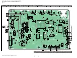
Page 50: ...9 F5 GPIO20 G5 GPIO21 F4 GPIO22 G3 GPIO23 G2 GPIO24 B2 GPIO25 B1 GPIO26 C2 GPIO27 AC24 SCL B3 SDA A3 UATXD AH26 UARXD AF25 RESET_ AF26 EFPWRQ H1 IR AH28 OPWRSB AH25 VOUTVSYNC L25 VOUTHSYNC L24 VOUTCLK P22 VOUTD0 W26 VOUTD1 W25 VOUTD2 V23 VOUTD3 R24 VOUTD4 V24 VOUTD5 V25 VOUTD6 U25 VOUTD7 U24 VOUTD8 R23 VOUTD9 U23 VOUTD10 T26 VOUTD11 U26 VOUTD12 P24 VOUTD13 P25 VOUTD14 P23 VOUTD15 P26 R1410 4 7k 75...

Page 51: ...ETRAYPWM C11 FEFG C9 AVDD12_1 E23 AVDD12_2 C15 AVDD33_1 F18 AVDD33_3 E18 AGND12_1 G21 AGND12_2 F19 AGND33_1 F20 AGND33_2 G18 AGND33_3 F17 FEEJECT_ D10 RSTI A22 FEGIO0 C10 FEGIO1 F13 FEGIO3 E8 FEGIO4 D7 FEGIO5 E13 FEGIO6 D9 FEGIO7 C7 FEGIO9 D6 FEGIO10 E10 FEGIO11 F7 1 C1121 4 7k R1707 0 01 C1707 FE_LOAD_N FE_LOAD_P 1 2 3 4 5 6 7 7P CN1701 FE_TILT FE_TR FE_FR FE_TILT FE_TR FE_FR FE_CO_A FE_CO_B FE_C...

Page 52: ...0RDFDRG4 1 SLED1_P 2 SLED1_N 3 P12V_3 4 SLED2_P 5 SLED2_N 6 PGND_2 7 C10V 8 CP1 9 CP2 10 CP3 11 GPOUT 12 XFG 13 RDY 14 SSZ 15 SCLK 16 SIMO 17 SOMI 18 SIOV 19 XRSTIN 20 TEST1 21 VLDDIN 22 CV3P3 23 AGND DGND 24 A9P5V 25 ILDD_BD 26 ILDD_DVD 27 ILDD_CD 28 CA5V 29 LOAD_P 30 LOAD_N 31 P5V12L 32 TEST2 33 TEST3 34 P5V_1 35 TLT_N 36 TLT_P 37 TRK_P 38 TRK_N 39 FCS_P 40 FCS_N 41 PGND_1 42 P12V_1 43 U 44 ICOM...

Page 53: ...KE_MODE NC NC NC VCC_3 3V NC VSS PLUG_DET NC DRIVER_SD PVDD_DET NC STA516_TH_WARN FL_CS ASEL0 ASEL1 NO USE NO USE ST_RDS_INT NO USE IF_SDO IF_SDI IF_SCK XIF_CS SRS_INT NC BD_RESET JIG_MODE1 OPWRSB FE_EJECT UPG_STATUS S AIR_RST S AIR_GPIO2 S AIR_DET BD_TEMP DESTINATION MODEL KEY2 KEY1 AVSS KEY0 VREF AVCC NO USE NO USE NO USE OPWRSB CL6376 DAMP_SCL DAMP_XPDN DAMP_XRST DAMP_XMUTE STA516_TH_WARN CL637...

Page 54: ...19 1 19 6 2 7 1 9 1 1 23 21 2 24 22 11 1 1 3 4 A K K A A K 5 A1 B1 C1 D1 E1 F1 G1 H1 J1 K1 L1 M1 N1 P1 R1 T1 A2 B2 C2 D2 E2 F2 G2 H2 J2 K2 L2 M2 N2 P2 R2 T2 A3 B3 C3 D3 E3 F3 G3 H3 J3 K3 L3 M3 N3 P3 R3 T3 A7 B7 C7 D7 E7 F7 G7 H7 J7 K7 L7 M7 N7 P7 R7 T7 A8 B8 C8 D8 E8 F8 G8 H8 J8 K8 L8 M8 N8 P8 R8 T8 A9 B9 C9 D9 E9 F9 G9 H9 J9 K9 L9 M9 N9 P9 R9 T9 A1 B1 C1 D1 E1 F1 G1 H1 J1 K1 L1 M1 N1 P1 R1 T1 A2 ...

Page 55: ...7 JL101 JL5301 JL102 JL5302 JL103 JL5303 R1810 JL104 JL5304 C120 JL2230 R1811 JL105 CL5901 JL5305 JL2231 C121 CL5902 JL106 JL5306 JL2232 C122 JL107 CL5903 JL5307 JL2233 JL108 C700 JL5308 JL2234 C124 JL109 JL5309 JL2235 C702 JL2236 C126 JL2237 JL2238 C128 R934 C705 JL2239 C129 R935 R936 C707 R937 JL110 JL5310 C708 R938 C709 JL111 JL5311 R939 JL5312 JL112 JL113 JL5313 JL114 JL2240 JL115 JL2241 C131 ...

Page 56: ...IRING BOARD FL Board FL Board Uses unleaded solder See page 42 for Circuit Boards Location 34 44 22 12 1 11 33 23 1 15 CL901 CL902 CL903 CL904 Q902 Q903 L901 1 2 4 29 31 32 ND901 FLUORESCENT INDICATOR TUBE R904 R908 R909 R910 R911 1 7 CN902 CN903 3 1 CN904 C902 C903 C904 C905 C908 C911 C912 C913 C915 C917 S901 INITIALIZE SKIP C926 C929 IC902 IC903 IC904 IC905 T901 DC DC CONVERTER TRANSFORMER R901 ...

Page 57: ... IC903 1 2 3 JL901 JL902 JL903 JL904 JL905 JL906 JL907 JL908 JL909 JL910 JL911 JL912 JL913 JL914 JL915 100 R910 100 R909 100 R908 50V 47 C917 16V 100 C908 1k R901 1 2 3 4 5 6 7 8 9 10 11 12 13 14 15 15P CN903 3 3V RXD TXD JIG_MODE1 JIG_MODE0 SIRCS_H SIRCS_V UNSW3 3V FFC8 GND FL_GND PANEL6V PCONT_FL FL_DOUT FL_CLK FL_CS 100k R912 L901 47uH 1 8k R904 JL916 JL917 JL918 JL919 JL920 120k R911 1 3 4 5 6...

Page 58: ...JL506 JL507 JL508 JL509 JL511 JL512 JL513 JL514 JL515 JL516 JL517 JL518 JL520 JL521 JL522 MB 149 BOARD CN6301 01P LED BOARD COMPONENT SIDE LED BOARD CONDUCTOR SIDE 1 885 213 11 11 1 885 213 11 11 A K A D330 K CHASSIS 1 885 218 11 11 1 885 218 11 11 FL BOARD CN904 02P SIRCS BOARD COMPONENT SIDE SIRCS BOARD CONDUCTOR SIDE 3 1 1 885 214 11 11 PWR_KEY BOARD SIDE A PWR_KEY BOARD SIDE B 1 885 214 11 11 ...

Page 59: ... S 1170B33UC OTSTFG IC501 1 CONT 2 VSS 3 NC 4 VIN 5 VOUT 50V 0 4A F501 1 2 3 4 5 6 7 8 9 10 11 12 13 13P CN501 WS 6V WS GND LRCK GND BCK GND SD SL SR PCONT1 I2C_SCL DETECT I2C_SDA RESET GPIO2 30P CN502 1 RESERVED 2 DETECT 3 RESERVE 4 NC 5 NC 6 LRCK_X 7 BCK_X 8 SDIO_X 9 LRCK_W 10 BCK_W 11 SDIO_W 12 GND 13 3 3V 14 3 3V 15 GND 16 GND 17 256FS 18 INT 19 PD OUT_Airoha 20 NC 21 I2C_SDA 22 I2C_CLK 23 RES...

Page 60: ... IC3102 D3503 C3333 D3504 C3334 C3336 R3310 R3311 R3312 C3156 C3157 TP3001 C3356 TP3002 C3357 TP3004 TP3006 TP3007 TP3008 TP3009 C3552 C3555 R3145 TP3201 Q3552 TP3202 C3557 Q3553 TP3203 R3148 Q3554 TP3010 TP3204 Q3555 TP3011 D3151 TP3015 TP3017 TP3018 C3561 R3345 TP3019 C3563 R3348 C3371 C3372 TP3020 D3351 TP3022 TP3025 R3161 R3162 C3574 C3381 C3382 R3361 R3555 L3051 R3556 TP3230 TP3231 R3560 R356...

Page 61: ...4 R3155 R3156 R3157 R3158 R3353 R3354 R3355 R3356 R3357 R3358 L3451 L3452 L3453 L3454 L3455 L3456 L3457 L3458 L3459 R3383 R3384 L3460 R3515 R3195 R3196 R3197 R3198 L3465 JL3001 L3466 JL3002 JL3004 JL3007 JL3008 R3395 JL3009 R3396 R3397 R3398 JL3010 JL3011 JL3012 JL3013 JL3015 JL3017 JL3018 JL3019 JL3405 JL3406 JL3407 JL3408 JL3020 JL3409 JL3022 JL3026 JL3411 JL3412 C3402 C3404 C3406 JL3053 C3408 J...

Page 62: ...139 100V C3317 0 022 C3315 0 1 100V C3322 0 022 C3320 0 1 100V 0 022 C3340 0 1 C3338 0 1 C3339 1SS388 D3504 1SS388 D3151 1SS388 D3351 1 2 3 4 5 6 7 8 9 10 11 12 13 14 15 16 17 18 19 20 21 22 23 24 24P CN3505 DGND AMP_D2 SL SR DGND AMP_D3 C SW DGND AMP_D1 FL FR DGND AMP_LRCK DGND AMP_BCK DGND AMP_MCK DGND DAMP_XMUTE DAMP_XPDN DAMP_XRST XWARN DC_DET SD EN DAMP_SDA D3 3V DMAP_SCL D3 3V DGND AMP_D3 C ...

Page 63: ...LLATOR 0 8V VA VCC 2 7V 1 2V VA VCC EA 0 4V INTERNAL REGULATOR IC308 TPS54225PWPR VFB 2 VREG5 3 VO 1 14 VCC 13 VIN UNDERVOLTAGE LOCKOUT EN LOGIC PROTECTION LOGIC 12 VBST 11 SW2 10 SW1 9 PGND2 8 PGND1 REFERENCE SOFTSTART VREG5 SS 4 GND 5 PG 6 EN 7 UVLO TSD XCON CONTROL ROGIC PWM OCP IN 1 EN 3 GND 2 OUT 6 CURRENT LIMITER EN BLOCK OSC CONTROL LOGIC AND TIMER BLOCKING CONTROL FLAG FLAG 4 ILIM 5 GATE D...

Page 64: ...ONVERTER PWM TRK_ENA LOAD_ENA PRE DRIVER FEED BACK TRAY LOCK DETECTION P5V12L 31 D A CONVERTER PWM TLT_ENA D A CONVERTER PWM ON CHIP THERMOMETER STP_ENA DIFF_TLT 53 STP1_N 52 STP1_P POWER FET PRE DRIVER 55 STP2_N 54 STP2_P D A CONVERTER PWM STP_ENA POWER FET PRE DRIVER 38 TRK_N 37 TRK_P 40 FCS_N 41 PGND_1 39 FCS_P 36 TLT_P 35 TLT_N 44 ICOM1 43 U 42 P12V_1 47 W 46 P12V_2 45 V 48 ICOM2 49 M COM POWE...

Page 65: ...303 S 1170B33UC OTSTFG IC5902 S T111B50MC OHJTFG IC5903 TC74VHC4052AFT EK VOUT VIN 5 ON OFF 4 1 VSS 2 NC 3 OVERCURRENT PROTECTION THERMAL SHUTDOWN REFERENCE VOLTAGE ON OFF CONTROL 4 5 1 2 ON OFF VOUT VIN VSS 3 NC OVER CURRENT PROTECTOR REFERENCE VOLTAGE CIRCUIT ON OFF CIRCUIT 0Y 1 Y COM 3 A 10 B 9 3X 11 0X 12 X COM 13 1X 14 2X 15 VCC 16 O I I O C 2Y 2 O I I O C 3Y 4 O I I O C 1Y 5 O I I O C INH 6 ...

Page 66: ...GND VCC 2 3 VDD DGND 4 5 LRCK 7 REFERENCE u1 64 DECIMATION FILTER WITH HIGH PASS FILTER SERIAL INTERFACE MODE FORMAT CONTROL FMT 12 VINR 14 VINL 13 MD1 11 MD0 10 DOUT 9 BCK 8 CLOCK TIMING CONTROL POWER SUPPLY SCKI 6 VREF 1 FL Board IC902 MM3404A33URE IC6303 PST8429UL GND 1 VDD 2 VREF OUT 4 CD 3 VOUT 3 CE 1 GND 2 VDD 4 VOLTAGE REFERENCE CURRENT LIMIT BIAS ...

Page 67: ...ER DIMMING CIRCUIT KEY DATA MEMORY 2 x 16 BITS 4 BIT LATCH 1 LED1 2 LED2 3 LED3 4 LED4 24 16 16 12 4 8 8 4 8 27 SEG14 KS14 29 SEG16 KS16 30 VEE 28 SEG15 KS15 8 31 SEG17 GRID12 33 SEG19 GRID10 32 SEG18 GRID11 23 SEG10 KS10 24 SEG11 KS11 25 SEG12 KS12 26 SEG13 KS13 22 SEG9 KS9 21 SEG8 KS8 20 SEG7 KS7 19 SEG6 KS6 18 SEG5 KS5 17 SEG4 KS4 16 SEG3 KS3 15 SEG2 KS2 14 SEG1 KS1 MULTIPLEXED DRIVER 34 SEG20 ...

Page 68: ...SEL 17 PDN 18 MUTE ASEL_EMO2 10 EMO1 15 DVDD2_CORE 14 DVSS2_CORE 13 AVDD 9 VR_ANA 8 OSC_RES 12 MCLK 11 19 SDA 20 AVSS 5 DEVICE CONTROL DIGITAL AUDIO PROCESSOR POWER SUPPLY SCL 21 AVSS_PWM 51 AVDD_PWM 50 PWM_P_1 39 PWM_M_1 38 PWM_P_2 41 PWM_M_2 40 PWM_P_3 43 PWM_M_3 42 PWM_P_4 45 PWM_M_4 44 PWM_P_7 47 PWM_M_7 46 PWM_P_8 49 PWM_M_8 48 PWM_P_5 54 PWM_M_5 53 PWM_P_6 56 PWM_M_6 55 LRCLKO 31 SCLKO 30 PS...

Page 69: ...G 28 RESET 16 HP_SEL 17 PDN 18 MUTE ASEL_EMO2 10 EMO1 15 DVDD2_CORE 14 DVSS2_CORE 13 AVDD 9 VR_ANA 8 OSC_RES 12 MCLK 11 19 SDA 20 AVSS 5 DEVICE CONTROL DIGITAL AUDIO PROCESSOR POWER SUPPLY SCL 21 AVSS_PWM 51 AVDD_PWM 50 PWM_P_1 39 PWM_M_1 38 PWM_P_2 41 PWM_M_2 40 PWM_P_3 43 PWM_M_3 42 N C 45 N C 44 N C 47 N C 46 PWM_P_4 49 PWM_M_4 48 N C 54 N C 53 N C 56 N C 55 LRCLKO 31 SCLKO 30 PSVC 33 VALID 37 ...

Page 70: ...T2A 8 VCC2A 7 GND2A 6 IN2B 32 M15 M17 IN2A 31 OUT1B 10 OUT1B 11 VCC1B 12 GND1B 13 M5 M4 OUT1A 17 N C 18 OUT1A 16 VCC1A 15 GND1A 14 IN1B 30 M2 M3 IN1A 29 VSS 34 VSS 33 VDD 22 VDD 21 GND_REG 20 GND_CLEARN 19 VCC_SIGN 36 VCC_SIGN 35 REGULATORS CONFIG 24 VL 23 TRISTATE 26 PWRON 25 TH_WARN 28 FAULT 27 PROTECTIONS LOGIC Ver 1 1 ...

Page 71: ...A27 AOSDATA4 O Digital audio signal output terminal A28 AR0 Not used B1 B2 GPIO25 GPIO24 Not used B3 SCL I O Two way I2C clock bus with the EEPROM Except Russian and Indian models B4 USB_DM_P1 I O Two way USB serial data with the wireless LAN card HBD N590 N790W N890W N990W T79 only B5 USB_DM_P0 I O Two way USB serial data with the USB connector front side B8 SRXP I Receive data positive input ter...

Page 72: ...t from the BD drive D9 FEGIO6 Not used D10 FEEJECT_ Not used D13 FEGAINSW3 Not used D14 FEOSCEN O Serial data transfer clock signal output to the BD drive D15 FEGAINSW1 O Mode A selection signal output to the BD drive D16 FE_TRAYIN_ I Disc tray out detection signal input from the BD drive D17 V14 Not used D18 INF I Sub beam F input from the BD drive D19 HAVC O Reference voltage output to the BD dr...

Page 73: ...ly terminal 3 3V G26 AVDD12_HDMI_D Power supply terminal 1 2V G27 CLK_P O TMDS clock positive signal output to the HDMI ARC OUT connector G28 CLK_M O TMDS clock negative signal output to the HDMI ARC OUT connector H1 EFPWRQ Not used H2 GPIO5 O Jig mode selection signal output to the system controller H3 GPIO9 Not used H4 DGND12_K Ground terminal H5 H6 DDRVCCIO1 Power supply terminal 1 5V H7 DGND12...

Page 74: ... data bus with the SD RAM M8 DDRVCCIO1 Power supply terminal 1 5V M10 DDRVCCK Power supply terminal 1 2V M11 to M18 DGND12_K Ground terminal M19 DVCC12_K Power supply terminal 1 2V M22 AVSS33_HDMI Ground terminal M27 HDMI_RX_2 I TMDS data positive input from the HDMI IN 1 connector M28 HDMI_RX_2B I TMDS data negative input from the HDMI IN 1 connector N1 RDQS3_B O Data strobe signal positive outpu...

Page 75: ...he SD RAM L reset T5 T6 RA4_B RA14_B O Address signal output to the SD RAM T7 DGND12_K Ground terminal T8 DDRVCCIO1 Power supply terminal 1 5V T10 DDRVCCK Power supply terminal 1 2V T11 to T18 DGND12_K Ground terminal T19 T20 DVCC12_K Power supply terminal 1 2V T22 AVSS33_VDAC_BG Ground terminal T26 VOUTD10 Not used T27 AVDD33_VDAC_BG Power supply terminal 3 3V U3 to U5 RA5_B RA3_B RA11_B O Addres...

Page 76: ...B_POP1 Ground terminal Y23 DGND12_K Ground terminal Y26 AVDD33_USB_P2 Power supply terminal 3 3V AA1 RDQS0__B O Data strobe signal negative output to the SD RAM AA2 RDQS0_B O Data strobe signal positive output to the SD RAM AA3 AA4 RDQ3_B RDQ11_B I O Two way data bus with the SD RAM AA5 RDQM1_B O Data mask signal output to the SD RAM AA6 RDQ15_B I O Two way data bus with the SD RAM AA7 DGND12_K Gr...

Page 77: ... Receive data negative input from the ethernet connector AC28 TXVP_1 I Receive data positive input from the ethernet connector AD1 RDQM0_B O Data mask signal output to the SD RAM AD2 AD3 RDQ6_B RDQ7_B I O Two way data bus with the SD RAM AD4 AVSS33_MEMPLL Ground terminal AD8 RA13 O Address signal output to the SD RAM AD9 RRESET O Reset signal output to the SD RAM L reset AD10 RCAS_ O Column addres...

Page 78: ... AF21 NFD6 I O Two way data bus with the NAND flash AF22 NFCEN O Chip enable signal output to the NAND flash AF23 NFD1 I O Two way data bus with the NAND flash AF24 NFALE O Address latch enable signal output to the NAND flash AF25 UARXD Not used AF26 RESET_ I Reset signal input from the system controller L reset AF27 DDC_SDA_RX I O Two way I2C data bus with the HDMI IN 1 connector AF28 DDC_SCL_RX ...

Page 79: ...output to the SD RAM AH13 RCKE O Clock enable signal output to the SD RAM AH14 RDQ2 I O Two way data bus with the SD RAM AH16 RDQS0_ O Data strobe signal negative output to the SD RAM AH17 RCLK0_ O Clock signal negative output to the SD RAM AH18 RDQS1 O Data strobe signal positive output to the SD RAM AH19 RDQM0 O Data mask signal output to the SD RAM AH20 RDQ6 I O Two way data bus with the SD RAM...

Page 80: ...cent indicator tube driver H power on 26 LED_PWM1 O LED drive signal output terminal 27 WS_SCL I O Two way I2C clock bus with the RF modulator EZW RT50 HBD N790W N890W N990W T79 or EZW RT20 HBD N995W HBD N790W N890W N990W N995W T79 only 28 WS_SDA I O Two way I2C data bus with the RF modulator EZW RT50 HBD N790W N890W N990W T79 or EZW RT20 HBD N995W HBD N790W N890W N990W N995W T79 only 29 TXD1 O No...

Page 81: ...t Russian and Indian models Reset signal output to the BD decoder NAND flash and EEPROM L reset Except Russian and Indian models 82 JIG_MODE1 I Jig mode selection signal input from the BD decoder 83 OPWRSB I Power control signal input from the BD decoder 84 FE_EJECT O Eject stop key input detection signal output terminal Not used 85 UPG_STATUS I UPG status signal input from the BD decoder 86 S AIR...

Page 82: ...ordering these items The mechanical parts with no reference number in the exploded views are not sup plied Color Indication of Appearance Parts Ex ample KNOB BALANCE WHITE RED Parts Color Cabinet s Color Abbreviation AUS Australian model CH Chinese model CND Canadian model E3 Middle East model E12 Indian model E15 Iranian model EA Saudi Arabia model MX Mexican model RU Russian model SP Singapore m...

Page 83: ...for SERVICE 53 X 2583 057 1 REFLECTOR TOUCH ASSY 54 A 1850 449 A PWR_KEY BOARD COMPLETE 55 4 279 245 01 SCREW DIA 2 6X8 BLACK BV 56 4 298 337 01 BUTTON POWER 1 Ref No Part No Description Remark Ref No Part No Description Remark 56 54 55 55 55 51 not supplied not supplied 52 53 Note When TOUCH board is defective exchange the complete mounted board ...

Page 84: ...ARD COMPLETE 102 3 077 331 62 BV3 3 CR 103 4 298 335 01 BRACKET SLOT Ref No Part No Description Remark Ref No Part No Description Remark BD drive section BSX 3 101 102 102 102 102 102 102 not supplied not supplied not supplied not supplied not supplied not supplied FL board section 103 ...

Page 85: ...ORE FFC3 1 827 996 61 WIRE FLAT TYPE 9 CORE LOM1 A 1839 907 A LOADING ASSY NX Including MS 486 board loading motor 0 OP1 8 820 452 03 OPTICAL PICK UP KEM480AAA C2RP1 for SERVICE Ref No Part No Description Remark Ref No Part No Description Remark FFC1 FFC3 OP1 LOM1 FFC2 155 154 151 152 152 153 153 153 153 152 152 not supplied not supplied Note Wires flat type for service is all straight Please bend...

Page 86: ...k Ref No Part No Description Remark switching regulator section 203 204 205 205 201 202 202 202 202 202 202 202 202 201 not supplied not supplied not supplied not supplied FFC8 WLC1 not supplied not supplied D D E E N590 N790W N890W N990W T79 N590 N790W N890W N990W T79 Note 2 When the wireless LAN card WLC1 is replaced refer to CHECKING METHOD OF NETWORK OPERATION on servicing notes page 9 Note 1 ...

Page 87: ...C1 1 837 345 11 CORD POWER SUPPLY TW 0 AC1 1 837 822 21 CORD POWER SUPPLY CH 0 AC1 1 839 012 11 CORD POWER SUPPLY E12 0 AC1 1 839 940 21 CORD POWER SUPPLY TH 0 ACP1 1 569 008 22 ADAPTOR CONVERSION PX 0 SWR1 1 474 368 11 SWITCHNING REGULATOR 3L382W 1 US CND AEP UK AUS CH SP TW TH 0 SWR1 1 474 368 21 SWITCHNING REGULATOR 3L382W E3 E12 E15 EA MX PX RU Ref No Part No Description Remark Ref No Part No ...

Page 88: ...RE N590 FFC7 1 828 325 61 WIRE FLAT TYPE 13 CORE N790W N890W N990W N995W T79 0 M1 1 855 144 11 FAN DC 60 SQUARE Ref No Part No Description Remark Ref No Part No Description Remark 303 304 FFC7 not supplied not supplied not supplied not supplied not supplied not supplied MB 149 board section M1 FFC4 308 309 309 310 310 N790W N890W N990W N995W T79 N590 N790W N890W T79 N590 N790W N890W T79 N590 N990W...

Page 89: ...E for SERVICE N990W E12 9 351 A 1866 006 A MB 149 BOARD COMPLETE for SERVICE N990W E3 9 351 A 1866 007 A MB 149 BOARD COMPLETE for SERVICE N990W E15 9 351 A 1866 008 A MB 149 BOARD COMPLETE for SERVICE N990W EA 9 351 A 1866 009 A MB 149 BOARD COMPLETE for SERVICE N990W SP 9 351 A 1866 010 A MB 149 BOARD COMPLETE for SERVICE N990W AUS 9 351 A 1866 011 A MB 149 BOARD COMPLETE for SERVICE N990W TH 9 ...

Page 90: ...809 11 METAL CHIP 100 5 1 10W R909 1 216 809 11 METAL CHIP 100 5 1 10W R910 1 216 809 11 METAL CHIP 100 5 1 10W R911 1 216 846 11 METAL CHIP 120K 5 1 10W R912 1 216 845 11 METAL CHIP 100K 5 1 10W SWITCH S901 1 786 726 11 SWITCH TACTILE INITIALIZE SKIP TRANSFORMER T901 1 697 104 11 DC DC CONVERTER TRANSFORMER Ref No Part No Description Remark Ref No Part No Description Remark When indicating parts ...

Page 91: ...PLETE for SERVICE N990W TW 9 A 1866 013 A MB 149 BOARD COMPLETE for SERVICE N990W MX 9 A 1870 869 A MB 149 BOARD COMPLETE for SERVICE N790W PX 9 A 1882 499 A MB 149 BOARD COMPLETE for SERVICE N890W RU CAPACITOR JUMPER RESISTOR C101 1 100 916 11 CERAMIC CHIP 0 1uF 10 16V C102 1 100 916 11 CERAMIC CHIP 0 1uF 10 16V C103 1 116 738 11 CERAMIC CHIP 1uF 10 6 3V C104 1 116 719 11 CERAMIC CHIP 10uF 10 6 3...

Page 92: ... 100 916 11 CERAMIC CHIP 0 1uF 10 16V C418 1 116 719 11 CERAMIC CHIP 10uF 10 6 3V C419 1 100 916 11 CERAMIC CHIP 0 1uF 10 16V C420 1 100 916 11 CERAMIC CHIP 0 1uF 10 16V C421 1 100 916 11 CERAMIC CHIP 0 1uF 10 16V C422 1 100 916 11 CERAMIC CHIP 0 1uF 10 16V C423 1 100 916 11 CERAMIC CHIP 0 1uF 10 16V C424 1 100 916 11 CERAMIC CHIP 0 1uF 10 16V C425 1 100 916 11 CERAMIC CHIP 0 1uF 10 16V C427 1 100...

Page 93: ...P 100uF 20 16V C1804 1 114 868 11 CERAMIC CHIP 0 1uF 10 50V C1805 1 116 735 11 CERAMIC CHIP 1uF 10 16V C5301 1 116 716 11 CERAMIC CHIP 10uF 10 16V C5302 1 116 716 11 CERAMIC CHIP 10uF 10 16V C5307 1 164 937 11 CERAMIC CHIP 0 001uF 10 50V C5310 1 100 916 11 CERAMIC CHIP 0 1uF 10 16V C5311 1 112 692 11 CERAMIC CHIP 1000PF 5 50V C5312 1 112 298 91 CERAMIC CHIP 1uF 10 16V C5313 1 112 777 11 CERAMIC CH...

Page 94: ...717 848 01 IC NCP380HSNAJAAT1G N590 N790W N890W N990W T79 IC700 6 702 302 01 IC TK11133CSCL G IC701 6 705 337 01 IC TK11150CSCL G IC901 6 707 010 01 IC NJM2740V IC1151 6 718 188 01 IC BD80GA3WEFJ E2 IC1201 6 718 022 11 IC TPIC2050RDFDRG4 IC1402 6 713 560 01 IC MFI341S2162 EXCEPT RU E12 IC1801 6 716 739 01 IC BD00GC0WEFJ SE2 IC5301 6 717 879 01 IC RT8293ALZSP IC5302 6 716 739 01 IC BD00GC0WEFJ SE2 ...

Page 95: ...RT CHIP 0 R631 1 218 965 11 METAL CHIP 10K 5 1 16W R700 1 216 864 11 SHORT CHIP 0 R702 1 218 990 81 SHORT CHIP 0 R703 1 216 864 11 SHORT CHIP 0 R708 1 218 990 81 SHORT CHIP 0 R711 1 218 953 11 METAL CHIP 1K 5 1 16W R713 1 218 953 11 METAL CHIP 1K 5 1 16W R750 1 218 973 11 METAL CHIP 47K 5 1 16W R751 1 218 956 11 METAL CHIP 1 8K 5 1 16W R752 1 218 956 11 METAL CHIP 1 8K 5 1 16W R753 1 218 953 11 ME...

Page 96: ...10W R1215 1 216 825 11 METAL CHIP 2 2K 5 1 10W R1216 1 216 825 11 METAL CHIP 2 2K 5 1 10W R1217 1 216 825 11 METAL CHIP 2 2K 5 1 10W R1218 1 216 825 11 METAL CHIP 2 2K 5 1 10W R1401 1 208 860 81 METAL CHIP 75 0 5 1 16W R1402 1 218 990 81 SHORT CHIP 0 R1403 1 218 990 81 SHORT CHIP 0 R1405 1 218 990 81 SHORT CHIP 0 R1410 1 218 961 11 METAL CHIP 4 7K 5 1 16W R1411 1 218 961 11 METAL CHIP 4 7K 5 1 16W...

Page 97: ...1 218 961 11 METAL CHIP 4 7K 5 1 16W R6341 1 218 941 81 METAL CHIP 100 5 1 16W R6342 1 218 990 81 SHORT CHIP 0 R6343 1 218 970 11 METAL CHIP 27K 5 1 16W R6347 1 218 965 11 METAL CHIP 10K 5 1 16W R6348 1 218 941 81 METAL CHIP 100 5 1 16W R6349 1 218 977 11 METAL CHIP 100K 5 1 16W R6350 1 218 977 11 METAL CHIP 100K 5 1 16W R6352 1 218 977 11 METAL CHIP 100K 5 1 16W R6354 1 218 965 11 METAL CHIP 10K ...

Page 98: ...0 154 91 CERAMIC CHIP 330PF 5 100V C3281 1 100 154 91 CERAMIC CHIP 330PF 5 100V C3282 1 100 154 91 CERAMIC CHIP 330PF 5 100V C3306 1 118 066 11 CERAMIC CHIP 0 1uF 10 100V C3307 1 118 066 11 CERAMIC CHIP 0 1uF 10 100V C3308 1 114 831 91 CERAMIC CHIP 1uF 10 100V C3309 1 114 831 91 CERAMIC CHIP 1uF 10 100V C3315 1 114 868 11 CERAMIC CHIP 0 1uF 10 50V N590 C3317 1 118 310 11 CERAMIC CHIP 0 022uF 10 10...

Page 99: ...Q3552 6 551 272 01 TRANSISTOR RT3CLLM Q3553 6 552 408 01 TRANSISTOR DSC500100L Q3554 6 552 760 01 FET SSM3J325F LSOYF Q3555 6 552 772 01 TRANSISTOR RT3AMMAM1 T111 1F RESISTOR R3021 1 208 713 11 METAL CHIP 18K 0 5 1 16W R3022 1 218 967 11 METAL CHIP 15K 5 1 16W R3023 1 218 949 11 METAL CHIP 470 5 1 16W R3024 1 218 949 11 METAL CHIP 470 5 1 16W R3025 1 218 965 11 METAL CHIP 10K 5 1 16W R3026 1 218 9...

Page 100: ...CHIP 100K 5 1 16W R3561 1 216 142 00 METAL CHIP 4 7 5 1 8W R3563 1 216 142 00 METAL CHIP 4 7 5 1 8W R3657 1 216 841 11 METAL CHIP 47K 5 1 10W R3658 1 216 833 11 METAL CHIP 10K 5 1 10W R3659 1 216 827 11 METAL CHIP 3 3K 5 1 10W COMPOSITION CIRCUIT BLOCK RB3001 1 234 372 11 RES NETWORK 100 1005X4 RB3002 1 234 372 11 RES NETWORK 100 1005X4 RB3003 1 239 409 11 RES CHIP NETWORK 47 3216 RB3303 1 234 381...

Page 101: ...1 CORD POWER SUPPLY E12 0 AC1 1 839 940 21 CORD POWER SUPPLY TH 0 ACP1 1 569 008 22 ADAPTOR CONVERSION PX FFC1 1 838 108 11 CABLE FLEXIBLE FLAT 45P FFC2 1 828 302 61 WIRE FLAT TYPE 7 CORE FFC3 1 827 996 61 WIRE FLAT TYPE 9 CORE FFC4 1 846 050 11 CABLE FLEXIBLE FLAT 22 CORE N790W N890W N990W N995W T79 FFC4 1 846 051 11 CABLE FLEXIBLE FLAT 24 CORE N590 FFC6 1 828 295 61 WIRE FLAT TYPE 7 CORE FFC7 1 ...

Page 102: ...102 HBD N590 N790W N890W N990W N995W T79 MEMO ...

Page 103: ...590 N790W N890W N990W N995W T79 US Model HBD N790W N890W T79 Canadian Model Russian Model Saudi Arabia Model Iranian Model Taiwan Model Middle East Model HBD N890W N990W AEP Model HBD N590 N790W N890W N990W UK Model HBD N590 N790W Australian Model HBD N590 N990W Chinese Model HBD N995W PX Model HBD N790W Mexican Model Thai Model Indian Model HBD N990W Singapore Model HBD N590 N890W N990W ...

Page 104: ...K OK Check the related IC on the MB 149 board OK OK Check each voltage with reference to the schematic diagrams and check that there is no problem in them OK Check that a picture is outputted normally NG Optimize the speaker settings NG Check that the drive is operating normally Continued on next page OK Refer to the 2 1 Flow of drive section check on page 6 on original service manual NG OK Check ...

Page 105: ... 103 01 IC TAS5538DGGR N790W N890W N990W N995W T79 Part No Description 6 718 105 01 IC TAS5534DGGR NG Check that the signal is outputted from the following pins AMP board IC3102 pin 10 11 SP FRONT R pin 16 17 SP FRONT L pin 2 3 8 9 SP SUBWOOFER OK Exchange the IC3102 Part No Description 6 718 443 01 IC STA516B13TR A NG Check that the signal is outputted from the following pins AMP board IC3302 pin...

Page 106: ...401 NG OK Check that the input voltage of the following pin is 6 V MB 149 board IC701 pin 5 VIN Refer to the 1 Power check flow on page 2 NG OK Check that the output voltage of the following pin is 5 V MB 149 board IC701 pin 4 VOUT Exchange the IC701 Part No 6 705 337 01 NG OK Check that only the digital output HDMI is affected Check the settings on the menu screen NG Description IC TK11150CSCL G ...

Page 107: ...MEMO HBD N590 N790W N890W N990W N995W T79 5 ...

Page 108: ...ion of COVER BOTTOM SMR 12003 1 2 2012 06 Addition of TROUBLESHOOTING SMR 12017 How to search for a contact point of signal lines or the like in DIAGRAMS SECTION If a contact point of a BLOCK DIAGRAM PRINTED WIRING BOARD or SCHEMATIC DIAGRAM is shown in a different page use the PDF file search function to find one e g If a contact point is shown as follow the procedure below Procedure 1 Press the ...

Reviews: