HBD-N590/N790W/N890W/N990W/N995W/T79
9
ADVANCE PREPARATION WHEN CONFIRMING OP-
ERATION
In order to perform the operation checking, all the units contained
in this unit are needed.
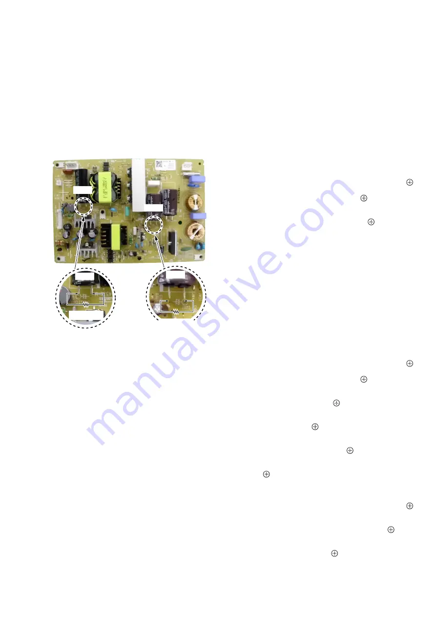
CAPACITOR ELECTRICAL DISCHARGE PROCESSING
When checking the board, the electrical discharge is necessary for
the electric shock prevention.
Connect the resistor to both ends of respective capacitors.
• Switching
regulator
C207,
C402
– SWITCHING REGULATOR (Component Side) –
C207
800
:
/2 W
800
:
/2 W
C402
C402
C207
CHECKING METHOD OF NETWORK OPERATION
(HBD-N590/N790W/N890W/N990W/T79 only)
It is necessary to check the network operation, when replacing the
MB-149 board or wireless LAN card (WLC1). Check the operation
of wireless and wired LAN, according to the following method.
1. Checking Method of Wireless LAN Operation
Check that access point is recognized surely.
Necessary Equipment:
Wireless access point with router function (AP)
Procedure:
1. Press the [HOME] button on the remote commander to enter
the home menu.
2. Press
the
[
m
]/[
M
]/[
<
]/[
,
] buttons on the remote command-
er to select “Setup”
“Network Settings”, and press the [ ]
button on the remote commander.
3. Select “Internet Settings”, and press the [ ] button on the re-
mote commander.
4. Press the [
m
]/[
M
] buttons on the remote commander to select
“Wireless Setup (built-in)”, and press the [ ] button on the
remote commander.
5. The system starts searching for access points, and displays a
list of up available network name (SSID).
6. Check that access point (SSID) is displayed on the searching
result.
7. Press the [
?/1
] button to turn the power off.
Note:
Refer to the instruction manual about details of the setting method.
2. Checking method of wired LAN operation
Check that access point is recognized surely.
Procedure:
1. Connect the main unit to the router or the hub, etc. with the
LAN cable.
2. Press the [HOME] button on the remote commander to enter
the home menu.
3. Press
the
[
m
]/[
M
]/[
<
]/[
,
] buttons on the remote command-
er to select “Setup”
“Network Settings”, and press the [ ]
button on the remote commander.
4. Select “Internet Settings”, and press the [ ] button on the re-
mote commander.
5. Press the [
m
]/[
M
] buttons on the remote commander to select
“Wired Setup”, and press the [ ] button on the remote com-
mander.
6. Press the [
m
]/[
M
] buttons on the remote commander to select
“Auto”, and press the [ ] button on the remote commander.
7. Press the [
,
] button on the remote commander.
8. Press the [
m
]/[
M
] buttons on the remote commander to select
“Save & Connect”, and press the [ ] button on the remote
commander.
9. When “Internet Settings is now complete.” appears, then press
the [ ] button on the remote commander.
10. Press the [HOME] button on the remote commander to enter
the home menu.
11. Press the [
m
]/[
M
]/[
<
]/[
,
] buttons on the remote command-
er to select “Setup”
“Network Settings”, and press the [ ]
button on the remote commander.
12. Press the [
m
]/[
M
] buttons on the remote commander to select
“Network Connection Diagnostics”, and press the [ ] button
on the remote commander.
13. Press the [
<
]/[
,
] buttons on the remote commander to
select “Start”, and press the [ ] button on the remote com-
mander.
14. Con
fi
rm that “Network connections are correct” is displayed.
15. Press the [
?/1
] button to turn the power off.
Note:
Refer to the instruction manual about details of the setting method.
Ver. 1.1


