background image

GTK-XB7

GTK-XB7

27

27

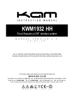
4-5.  SCHEMATIC  DIAGRAM - MAIN Board (2/8) -

A

3

8

6

E

2

9

D

5

B

C

7

1

4

(2/8)

MAIN BOARD

C54


10uF

C54


10uF

R46

1K

R46

1K

R55

10K

R55

10K

R53

10K

R53

10K

C102

0.1uF/16V/X7R

C102

0.1uF/16V/X7R

Q5

NPN_3DG3904M

Q5

NPN_3DG3904M

D18

LL4148

D18

LL4148

TP14

TP14

RESET

3.3V_D2

MPEG_RST

MPEG_RST

1

2

3

4

NC

RFIS

AGCCAP AD_AVDD AD_AVSS

LDSW/GPIO67 HOME/GPIO66

VDD_12 CLKOUT

CLKIN

PLL_VDD PLL_VSS

USB_AVSS

USB_DM USB_DP

ADAC_AVSS

AOUT_L

USB_AVDD

VDD_12

TV_AVSS TV_DAC3 TV_DAC2 TV_DAC1 TV_AVDD TV_AVSS TV_AVDD TV_DAC0 V_FSADJ V_COMP AOUT_R

ADAC_AVDD

GPIO86

M_A5

VREF

SPDIF_IN/GPIO48

SPDIF_OUT/GPIO47

M_A3

M_A2

M_A1

M_A0

M_A10

M_BA1

M_RAS

M_CAS

M_WE

M_DQM0

M_A4

VFD_CLK VFD_STB VFD_DATA VDD_33 RESET_B VSS IR_IN/GPIO3 GPIO4 GPIO5 VDD_12 HSYNC/GPIO7 VSYNC/GPIO8 M_D0 M_D1 M_D2 M_D3 M_D4 M_D5 M_D6 M_D7 M_D15 M_D14 M_D13 M_D12 M_D11 M_D10 M_D9 M_D8 M_DQM1 VSS M_CLK VDD_33 M_A11 M_A9 M_A8 M_A7 M_A6

CDLDO

NC

CDMDI

SRV_AVDD

V21

V165

DA_AVSS

DA_TEO

DA_FEO

DA_AVDD

SPDC_OUT/GPIO70

SC_OUT/GPIO71

GPIO72

DMEA

CARD_SENSE/GPIO74

SD_D0/GPIO75

SD_CLK/GPIO76

SD_SMD/GPIO77

GPIO78

GPIO79

CDVR

SPI_CE

SPI_D0

SPI_CLK

SPI_D1

APC_AVSS

OPVIN OPVIP

E F A B C D

RFSUM

AIN_R

AD_AVDD

AD_AVSS

GPIO54

GPIO53

GPIO52

GPIO51

GPIO50

M_BA0

CE#

SO

WP#

VSS

SI

SCK

HOLD#

VDD

FB8

500/200mA

FB8

500/200mA

C5

2


0.

1U
F

C5

2


0.

1U
F

TP12

TP12

C68


0.

1U
F

C68


0.

1U
F

C80


0.1UF

C80


0.1UF

C4

4

100pF/

50V/

N

P0

C4

4

100pF/

50V/

N

P0

R133

33

R133

33

TP58

TP58

C72


4.7UF

C72


4.7UF

R52

33

R52

33

C81


0.1UF

C81


0.1UF

MCLK_1

MCLK_1

R90

33

R90

33

R6

5

0R

65

0

TP7

TP7

R45

33

R45

33

BCLK_1

BCLK_1

C5

6


0.

1U
F

C5

6


0.

1U
F

R68

2.2

R68

2.2

C58

10uF/6.3V/X5R

C58

10uF/6.3V/X5R

C325

1

0

u

F

/6

.3

V

/X

5

R

C325

1

0

u

F

/6

.3

V

/X

5

R

LRCLK_1

LRCLK_1

C5

5


0.

1U
F

C5

5


0.

1U
F

R127

33

R127

33

R56

33

R56

33

R41

10K

R41

10K

C67


0.

1U
F

C67


0.

1U
F

R240

0

R240

0

TP8

TP8

R71

10K

R71

10K

XP2

4PIN/2.0mm

XP2

4PIN/2.0mm

R91

33

R91

33

C4

2

100pF/

50V/

N

P0

C4

2

100pF/

50V/

N

P0

FB9

500/200mA

FB9

500/200mA

TP10

TP10

R40

10K

R40

10K

R59
1K

R59
1K

R70
10K

R70
10K

TP4TP4

C129

5.

6pF/

5

0V/
N

P0

C129

5.

6pF/

5

0V/
N

P0

C7


0.1UF

C7


0.1UF

R32

1K

R32

1K

U6

SPHE8104W-128

U6

SPHE8104W-128

R6

4

33

R

64

33

C71


0.1UF

C71


0.1UF

C82

1000pF/50V/X7R

C82

1000pF/50V/X7R

Y1

27MHz/30PPM

Y1

27MHz/30PPM

R39

10K

R39

10K

R30

1K

R30

1K

C78


0.1UF

C78


0.1UF

C70


4.7UF

C70


4.7UF

TP3TP3

C130

5.

6pF/

5

0V/
N

P0

C130

5.

6pF/

5

0V/
N

P0

R241

0

R241

0

R89

4.7K

R89

4.7K

U5

KH25L1606 16M FLASH

U5

KH25L1606 16M FLASH

R62

0

R62

0

C64


4.7UF

C64


4.7UF

C7

3


0.

1U
F

C7

3


0.

1U
F

TP6

TP6

C4

3

100pF/

50V/

N

P0

C4

3

100pF/

50V/

N

P0

DATA_IN_1

DATA_IN_1

R98

4.7K

R98

4.7K

C5

7

1000pF/

50V/

X

7R

C5

7

1000pF/

50V/

X

7R

TP13

TP13

R50

33

R50

33

C63


4.7UF

C63


4.7UF

C4

5


0.

1U
F

C4

5


0.

1U
F

R112

4.7K

R112

4.7K

C66

5.

6pF/

5

0V/
N

P0

C66

5.

6pF/

5

0V/
N

P0

R3

6

1K

R

36

1K

C59


0.1UF

C59


0.1UF

C40

33pF/50V/NP0

C40

33pF/50V/NP0

C65


4.7UF

C65


4.7UF

C77

5.6pF/50V/NP0

C77

5.6pF/50V/NP0

C49


10UF/6.3V/X5R

C49


10UF/6.3V/X5R

R42

33

R42

33

R139

4.7K

R139

4.7K

C46


0.1UF

C46


0.1UF

C7

4


0.

1U
F

C7

4


0.

1U
F

C39

33pF/50V/NP0

C39

33pF/50V/NP0

R66

33

R66

33

R167

4.7K

R167

4.7K

TP5TP5

R242

0

R242

0

TP59

TP59

R33

33

R33

33

C76


0.1UF

C76


0.1UF

FB12

500/200mA

FB12

500/200mA

R73

1K

R73

1K

R31

100K

R31

100K

TP9

TP9

R49

33

R49

33

C88


4.7UF

C88


4.7UF

TP60

TP60

R37

1K

R37

1K

C5

3

10uF/

6.

3V/

X5R

C5

3

10uF/

6.

3V/

X5R

R54

33

R54

33

100uF/16V/SMD

CE9

100uF/16V/SMD

CE9

R51
33

R51
33

R74

1K

R74

1K

SDRAM

FLASH

SD33

AD_VCC3

RF3.3V

AVCC3

3.3V_D2

D33

AVCC3

D3

3

VCC1

.2

D3

3

VCC1

.2

R

F

3.

3V

VCC1.2

D33

RF3.3V

RFDA3.3V

VVCC3

VVCC3

VVCC3

VVCC3

F3V3

F3V3

F3V3

3.3V_D2

D33

D3

3

VCC1

.2

D3

3

RF3.3V

RFDA3.3V

STB_3.3V

AD_VCC3

STB_3.3V

1.2V_D

D33

1

2

3

4

103

92 91 90 89 88 87 86 85 84 83 82 81 80 79

64

65

78 77 76 75 7

4

73 72 71 70 69 68 67 66

63

1

39

62

53

52

51

50

49

48

47

46

44

43

42

41

40

2 3 4 5 6 7 8 9

10 11 12 13 14 15 16 17 18 19 20 21 22 23 24 25 26 27 28 29 30 31 32 33 34 35 36 37 38

104

105

106

107

108

109

110

111

112

113

114

115

116

117

118

119

120

121

122

123

124

125

126

127

128

102 101 100 99 98 97 96 95 94 93

61

60

59

58

57

56

55

54

45

1

2

3

4

5

6

7

8

Close to 8104WW

Close to SDRAM

Close to 8104WW

Close to 8104WW

Close to 8104WW

Put these circuits as
closer as possible to 
MPEG DECODER.

XI

V_FSADJ

XO

DEBUG_RX

DEBUG_TX

USB_DP

USB_DM

SF_CK

SPI_D0

SPI_D1

I2S_MCLK
I2S_BCLK
I2S_LRCK
I2S_DATA_IN

M_BA[0..1]

M_DQM[0..1]

RAM_CLK

M_A[0..11]
M_D[0..15]

M_RAS

M_CAS

M_WE

SF_CS

XI

I2C_SDA

I2C_SCL

DAC_VREF

M_A10

M_A2
M_A1

M_RAS

M_CAS

M_A0

M_A4

M_DQM0

M_BA0

M_WE

M_BA1

M_A3

M_A5

M_

A

9

M_

A

6

M_

A

7

M_

A

8

M

_A1

1

G

PIO2

5

RAM_CLK

M_

D

1

M_

D

3

M_

D

7

M_

D

6

M_

D

0

M_

D

4

M_

D

11

M_

D

14

M_

D

5

M_

D

12

M_

D

2

M_

D

9

M_

D

13

M_

D

10

M_

D

15

M_

D

8

M_

D

Q

M1

I2

S_

LR

CK

I2

S_BCLK

I2

S_

M

C

LK

M

PEG_RST

I2

S_

DATA_

IN

SF_CS
SPI_D0
SF_CK
SPI_D1

MPEG_RX

debug_TX

M

PEG_RX

debug_R

X

M

PEG_TX

XO

MCU_SDA

MCU_SCL

I2C_SW

BT_TX

BT_RX

MPEG_TX

AMP_FAULT

I2C_SCL
I2C_SDA

DQM[0..1]

(3)

MA[0..11]

(3)

DQ[0..15]

(3)

BA[0..1]

(3)

CAS#

(3)

WE#

(3)

DCLK

(3)

RAS#

(3)

USB_DM USB_DP

DSP_SCL

DSP_SDA

I2C1_SDA

I2C1_SCL

BT_RX 8

BT_TX 8

AOUT_R
AOUT_L

DATA6

AD_LRCK

AD_BCLK

AD_MCLK

I2C_SCL
I2C_SDA

AMP_RESET 11

AMP_FAULT

I2C_SW

SRC_MCLK
SRC_BCLK
SRC_LRCK

I2

S_

DATA_

O

UT

BT_MFB_MPEG

RF

SDRAM

Internal DA

Internal AD

Digital

Crystal

Video DAC

++

Summary of Contents for GTK-XB7

Page 1: ...trol Profile SPP Serial Port Profile Supported codecs SBC Sub Band Codec AAC Advanced Audio Coding LDAC 1 The actual range will vary depending on factors such as obstacles between devices magnetic fields around a microwave oven static electricity reception sensitivity antenna s performance operating system software application etc 2 BLUETOOTH standard profiles indicate the purpose of BLUETOOTH com...

Page 2: ...iPad Air and iPad mini are trademarks of Apple Inc App Store is a service mark of Apple Inc s Made for iPod Made for iPhone Made for iPad mean that an electronic accessory has been designed to connect specifically to iPod iPhone or iPad respectively and has been certified by the developer to meet Apple performance standards Apple is not responsible for the operation of this device or its complianc...

Page 3: ...c Diagram MAIN Board 5 8 30 4 9 Schematic Diagram MAIN Board 6 8 31 4 10 Schematic Diagram MAIN Board 7 8 32 4 11 Schematic Diagram MAIN Board 8 8 33 4 12 Printed Wiring Board BT NFC Board 34 4 13 Schematic Diagram BT NFC Board 34 4 14 Printed Wiring Board USB KEY Board 35 4 15 Schematic Diagram USB KEY Board 35 4 16 Printed Wiring Board IR Board 35 4 17 Schematic Diagram IR Board 35 4 18 Printed ...

Page 4: ... prone to flow than ordinary solder so use caution not to let solder bridges occur such as on IC pins etc Usable with ordinary solder It is best to use only unleaded solder but unleaded solder may also be added to ordinary solder REPAIRING THE BOARDS When each boards installed in this unit are defective replace the mounted board Individual electrical parts that mounted on the each boards cannot be...

Page 5: ... 2 16 RGBE BOARD Page 17 2 19 TWEETER SP3 SP4 Page 19 2 17 IR BOARD Page 18 2 20 WOOFER SP1 SP2 Page 20 2 10 MAIN CHASSIS BLOCK Page 12 2 8 CONTROL BOARD Page 10 2 11 BOTTOM COVER PLATE Page 13 2 12 FRONT PANEL BLOCK Page 14 2 4 PSU BOARD Page 7 2 3 FAN UNIT M1 Page 7 2 7 BT NFC BOARD Page 9 2 5 MAIN BOARD Page 8 2 6 USB KEY BOARD Page 9 JIG When disassembling the unit use the following jig for sp...

Page 6: ...e FFC to MAIN OH LEOH IODW FDEOH WR 0 1 VHWWLQJ XP35 1 two rubber large circle 2 two rubber circle 5 two rubber small circle 7 two rubber square 3 two screws 3 screw 4 three screws 3 screw 3 two screws 6 two screws 8 two screws 9 Remove the top cover block in the direction of the arrow qa top cover block front side The opposite side is the terminal side ...

Page 7: ...N UNIT M1 2 4 PSU BOARD 1 connector XP14 2 screw 3 fan unit M1 2 screw 1 two screws hole boss boss boss boss hole hole ditch 5 five screws 6 PSU board 3 connector XP1 4 connector CN501 2 reinforcement bracket Rear view ...

Page 8: ...nnector XP10 6 connector XP22 1 connector XP37 2 connector XP7 3 connector XP14 qa four screws qd MAIN board 0 screw qs Remove the MAIN board in the direction of the arrow LUH VHWWLQJ front side rear side MAIN board XP21 XP22 XP37 XP7 XP14 XP45 XP36 XP10 XP25 flexible flat cable The opposite side is the terminal side ...

Page 9: ...e to MAIN flexible flat cable to MAIN 4 flexible flat cable FFC to BT NFC XP8 2 Peel off the adhesive sheet 5 BT board adhesive sheet 6 BT NFC board claw top cover block OH LEOH IODW FDEOH WR 0 1 VHWWLQJ Note Connect the side of short reinforcement plate to the BT NFC board front side rear side top side The opposite side is the terminal side ...

Page 10: ...ible flat cable FFC to BT NFC XP16 1 connector XP8 2 eight screws 6 CONTROL board 3 plate 4 Remove the CONTROL board block in the direction of the arrow top cover block front side rear side top side The opposite side is the terminal side ...

Page 11: ... bond and use a new bond to fix the side panel L 5 side panel R Note When installing the side panel R remove the used bond and use a new bond to fix the side panel R 3 screw 1 two rubber circle 2 screw 1 rubber large circle bond 1 rubber large circle 4 Remove the side panel L in the direction of the arrow 4 Remove the side panel R in the direction of the arrow Rear view ...

Page 12: ...XP21 2 connector XP10 3 connector XP22 5 connector XP36 6 connector XP25 4 flexible flat cable XP45 7 seven screws 8 main chassis block LUH VHWWLQJ front side MAIN board XP21 XP22 XP10 XP25 flexible flat cable XP45 XP36 The opposite side is the terminal side ...

Page 13: ...rrow bond RZ WR UHPRYH WKH ERWWRP FRYHU SODWH Note 1 When removing the bottom cover plate move the bottom cover plate slowly and remove the bond as shown figure Note 2 When removing the bottom cover plate please remove carefully so as not to damage the bosses 8 bottom cover plate Note 3 When installing the bottom cover plate remove the used bond and use a new bond to fix the bottom cover plate top...

Page 14: ...d while moving jig in the direction of the arrow and front panel block is removed 5 All bosses are removed while moving jig in the direction of the arrow and front panel block is removed front panel block 7 tweeter terminal narrow side 7 tweeter terminal wide side 1 screw 1 screw 2 four screws 3 prop bottom 6 Remove the front panel block in the direction of the arrow 8 front panel block Note 2 Whe...

Page 15: ...GTK XB7 15 2 13 LB BOARD 1 eight screws 3 connector XP56 5 connector XP50 6 LB board 4 connector XP37 2 Remove the LB board block in the direction of the arrow front panel block front side bottom side ...

Page 16: ...three screws 7 connector XP54 8 connector XP55 3 prop upper 2 Draw two cables out from the hole 0 cable 6 flexible flat cable XP38 flexible flat cable 5 Remove the LA board block in the direction of the arrow front panel block front side top side front panel block two cables LA board LUH VHWWLQJ LUH VHWWLQJ XP54 XP55 URQW YLHZ The opposite side is the terminal side ...

Page 17: ...WR LQVWDOO WKH 5 ERDUG Make sure that the projection of the RGBF board is out front panel block front side bottom side mounting plate bottom left Install the RGBE board into the slot boss 3 RGBE board 1 two screws 2 mounting plate bottom left hole Rear bottom view RZ WR LQVWDOO WKH 5 ERDUG Make sure that the projection of the RGBE board is out slot front panel block front side top side ...

Page 18: ... TWEETER SP5 1 screw 2 IR board 3 flannel front panel block front side top side 3 tweeter terminal narrow side 3 tweeter terminal wide side 1 two screws 2 speaker plate 4 speaker unit TW SP5 front panel block front side bottom side ...

Page 19: ... TWEETER SP3 SP4 3 tweeter terminal narrow side 3 tweeter terminal wide side 1 two screws 5 two screws 2 speaker plate 6 speaker plate 4 speaker unit TW SP3 7 speaker unit TW SP4 front panel block front side top side ...

Page 20: ... 1 four screws 1 four screws URQW YLHZ QVWDOODWLRQ GLUHFWLRQ IRU WKH VSHDNHU XQLW 63 63 terminals position top side woofer terminal wide side woofer terminal narrow side speaker unit WF SP1 speaker unit WF SP1 front side woofer terminal wide side woofer terminal narrow side speaker unit WF SP2 front side Note When installing the speaker unit WF SP1 SP2 make sure that there is a position of the spe...

Page 21: ... 1 LED blinks 1 time the EXTRA BASS LED blinks 5 times When the MPEG version is v07 the AUDIO IN LED blinks 0 time the USB LED blinks 7 times When the BT version is v075 the SPEAKER ADD L LED blinks 0 time the SPEAKER ADD R LED blinks 7 times the PARTY CHAIN LED blinks 5 times FACTORY RESET It can reset all MPEG settings and clear the Bluetooth linked list Execute this mode when returning the this...

Page 22: ...MEMO GTK XB7 22 MEMO ...

Page 23: ...GTK XB7 GTK XB7 23 23 SECTION 4 DIAGRAMS 4 1 BLOCK DIAGRAM OVERALL Section ...

Page 24: ...les seeing The other layers patterns are not indicated Circuit Boards Location Caution Pattern face side Conductor Side Parts face side Component Side Parts on the pattern face side seen from the pattern face are indicated Parts on the parts face side seen from the parts face are indicated Note The components identi fied by mark 0 or dotted line with mark 0 are criti cal for safety Replace only wi...

Page 25: ... XB7 GTK XB7 25 25 4 3 PRINTED WIRING BOARD MAIN Board Uses unleaded solder See page 24 for Circuit Boards Location MAIN BOARD COMPONENT SIDE MAIN BOARD CONDUCTOR SIDE A B C D E F G H I J 1 2 3 4 5 6 7 8 9 ...

Page 26: ... 3 5 2 1 4 3 5 2 input Vout ADJ GND Out 1 2 3 4 5 6 7 8 9 G D S G D S G D S VIN SS EN GND VOUT C114 NC 330pF 50V X7R C114 NC 330pF 50V X7R R5 200K 1 R5 200K 1 C14 10uF C14 10uF 470uF 10V CE2 470uF 10V CE2 R206 220K R206 220K D1 SS34 40V 3A D1 SS34 40V 3A R4 51K 1 R4 51K 1 C25 0 1uF 16V X7R C25 0 1uF 16V X7R R75 4 7K R75 4 7K C152 3900pF 50V X7R C152 3900pF 50V X7R C109 330pF 50V X7R C109 330pF 50V...

Page 27: ...73 0 1UF C73 0 1UF TP6 TP6 C43 100pF 50V NP0 C43 100pF 50V NP0 DATA_IN_1 DATA_IN_1 R98 4 7K R98 4 7K C57 1000pF 50V X7R C57 1000pF 50V X7R TP13 TP13 R50 33 R50 33 C63 4 7UF C63 4 7UF C45 0 1UF C45 0 1UF R112 4 7K R112 4 7K C66 5 6pF 50V NP0 C66 5 6pF 50V NP0 R36 1K R36 1K C59 0 1UF C59 0 1UF C40 33pF 50V NP0 C40 33pF 50V NP0 C65 4 7UF C65 4 7UF C77 5 6pF 50V NP0 C77 5 6pF 50V NP0 C49 10UF 6 3V X5R...

Page 28: ...im 2 25A_min 2 5A_typ Compatible for footprint CHG_EN BT_update_EN USB sync MODE USB charge USB_EN BT sync H X H L L H L H L SD33 SD33 SD33 SD33 USB_VCC1 USB_5V STB_3 3V USB_VCC1 STB_3 3V STB_3 3V 1 2 3 4 5 6 7 8 9 10 1 5 3 4 2 6 1 2 3 4 5 6 4 1 3 2 1 2 3 4 1 2 3 4 1 2 3 4 5 6 7 8 9 10 1 2 4 12 5 7 9 8 10 46 11 13 15 16 17 18 19 35 22 23 24 25 26 14 41 29 30 31 32 33 34 36 37 38 39 40 43 42 44 52 ...

Page 29: ...1UF FB61 220 FB61 220 C230 100pF 50V NP0 C230 100pF 50V NP0 C250 100pF 50V NP0 C250 100pF 50V NP0 R122 33 R122 33 R216 1M R216 1M R128 4 7K R128 4 7K XP46 18PIN 1 0mm XP46 18PIN 1 0mm FB66 220 FB66 220 C231 100pF 50V NP0 C231 100pF 50V NP0 R125 33 R125 33 C248 100pF 50V NP0 C248 100pF 50V NP0 R120 33 R120 33 FB54 220 FB54 220 C113 30pF 50V NPO C113 30pF 50V NPO R132 4 7K R132 4 7K FB62 220 FB62 22...

Page 30: ...2 220 C327 0 1UF C327 0 1UF XP35 45PIN 0 5MM XP35 45PIN 0 5MM C343 0 1UF C343 0 1UF C308 100pF 50V NP0 C308 100pF 50V NP0 C354 0 1UF C354 0 1UF FB73 220 FB73 220 R237 4 7K R237 4 7K R825 33 R825 33 C328 10uF C328 10uF C309 100pF 50V NP0 C309 100pF 50V NP0 C358 NC 15pF 50V NP0 C358 NC 15pF 50V NP0 FB74 220 FB74 220 C310 100pF 50V NP0 C310 100pF 50V NP0 R228 47 R228 47 R365 1K R365 1K C361 15PF C361...

Page 31: ...X5R C191 10uF 6 3V X5R C62 10uF 6 3V X5R C62 10uF 6 3V X5R R353 82K R353 82K R315 56K R315 56K C134 470K C134 470K R371 NC 33 R371 NC 33 R222 4 7K R222 4 7K C171 1000pF 50V X7R C171 1000pF 50V X7R R407 1M R407 1M R301 10K R301 10K R224 100 R224 100 R83 0 R83 0 FB80 500 800mA FB80 500 800mA C83 10uF 6 3V X5R C83 10uF 6 3V X5R R354 68K R354 68K C133 100pF 50V NP0 C133 100pF 50V NP0 R187 NC R187 NC R...

Page 32: ...PF C200 NC 12PF C200 NC 12PF R231 NC 47K R231 NC 47K R285 NC 33 R285 NC 33 R230 33 R230 33 R413 0 R413 0 C205 0 1UF C205 0 1UF R376 33 R376 33 C201 NC 12PF C201 NC 12PF R392 0 R392 0 C202 NC 12PF C202 NC 12PF C208 0 1UF C208 0 1UF C142 10uF 6 3V X5R C142 10uF 6 3V X5R C151 NC 12PF C151 NC 12PF C147 10uF 6 3V X5R C147 10uF 6 3V X5R R279 100 R279 100 R387 0 R387 0 C212 0 1UF C212 0 1UF R288 4 7K R28...

Page 33: ...3 0 1uF C289 1uF 63V C289 1uF 63V C329 270pF 50V X7R C329 270pF 50V X7R C264 0 1uF C264 0 1uF C531 10uF C531 10uF C265 0 033uF 50V X7R C265 0 033uF 50V X7R C332 1uF C332 1uF R363 10K R363 10K R774 220K R774 220K XP21 2PIN_3 96mm XP21 2PIN_3 96mm R319 NC 5 6 R319 NC 5 6 C50 10uF 6 3V X5R C50 10uF 6 3V X5R R783 100K R783 100K R298 4 7K R298 4 7K C530 10uF C530 10uF C280 0 1uF C280 0 1uF R60 47K R60 ...

Page 34: ...358 15pF 50V NP0 XP8 16pin 1 0 XP8 16pin 1 0 C355 15pF 50V NP0 C355 15pF 50V NP0 R220 33 R220 33 R922 0 R922 0 TM18 TM18 U26 SGM803 U26 SGM803 R110 33 R110 33 U7 MN63Y1212 U7 MN63Y1212 C111 0 1UF C111 0 1UF C124 NC 0 1uF 25V X5R C124 NC 0 1uF 25V X5R C2 120pF 50V NP0 C2 120pF 50V NP0 R108 33 R108 33 R223 33 R223 33 C359 15pF 50V NP0 C359 15pF 50V NP0 R378 NC 0 R378 NC 0 R918 0 R918 0 TM11 TM11 C18...

Page 35: ...59 220 R460 220 R460 220 R25 4 7K R25 4 7K C317 47pF 50V NP0 C317 47pF 50V NP0 C10 0 1uF C10 0 1uF LED8 LED_GREEN LED8 LED_GREEN C2 10uF C2 10uF R39 20K R39 20K R40 47K R40 47K C11 0 1uF C11 0 1uF FB39 500 800mA FB39 500 800mA USB 2 2V 2 72V L s t r a p d l o M R USB_5V USB_5V USB_5V USB_5V 1 2 3 4 1 2 3 4 6 5 1 2 3 4 5 6 PARTY CHAIN PARTY CHAIN ADD SPK ADD SPK DP DN ADC_KEY1 Blue_LED5 Blue_LED6 B...

Page 36: ...7 GTK XB7 36 36 4 18 PRINTED WIRING BOARD CONTROL Board Uses unleaded solder See page 24 for Circuit Boards Location CONTROL BOARD COMPONENT SIDE CONTROL BOARD CONDUCTOR SIDE A B C D E F 1 2 3 4 5 6 7 8 9 10 ...

Page 37: ...0 1uF LED4 LED_BULE LED4 LED_BULE C312 47pF 50V NP0 C312 47pF 50V NP0 ESD6 NC EGA10603V05A1 B ESD6 NC EGA10603V05A1 B R457 220 R457 220 C21 47pF 50V NP0 C21 47pF 50V NP0 R456 220 R456 220 R453 1K R453 1K C311 47pF 50V NP0 C311 47pF 50V NP0 C3 0 1uF C3 0 1uF Q12 NPN_3DG3904M Q12 NPN_3DG3904M R809 0 R809 0 R36 10K R36 10K C313 47pF 50V NP0 C313 47pF 50V NP0 XP16 16PIN 1 0mm XP16 16PIN 1 0mm SW2 SW2 ...

Page 38: ...er See page 24 for Circuit Boards Location LA BOARD COMPONENT SIDE LA BOARD CONDUCTOR SIDE A B C D E F 1 2 3 4 5 6 7 8 9 4 21 PRINTED WIRING BOARD RGBE Board Uses unleaded solder See page 24 for Circuit Boards Location RGBE BOARD COMPONENT SIDE RGBE BOARD CONDUCTOR SIDE A 1 2 ...

Page 39: ...56 3900pF 50V X7R C156 3900pF 50V X7R C238 100pF 50V NP0 C238 100pF 50V NP0 FB30 120 2A FB30 120 2A LED6 LED6 Q37 PNP_MMBT8550C Q37 PNP_MMBT8550C R902 0 R902 0 R456 100 R456 100 R861 500 200mA R861 500 200mA C15 10uF C15 10uF LED3 LED3 C191 0 1uF C191 0 1uF XP55 10PIN 1 25mm XP55 10PIN 1 25mm R798 0 R798 0 R851 0 R851 0 R465 22ohm R465 22ohm R384 6 8K R384 6 8K R901 0 R901 0 C346 100pF 50V NP0 C34...

Page 40: ...er See page 24 for Circuit Boards Location LB BOARD COMPONENT SIDE LB BOARD CONDUCTOR SIDE A B C D E F 1 2 3 4 5 6 7 8 9 4 25 PRINTED WIRING BOARD RGBF Board Uses unleaded solder See page 24 for Circuit Boards Location RGBF BOARD COMPONENT SIDE RGBF BOARD CONDUCTOR SIDE A 1 2 ...

Page 41: ...00pF 50V NP0 C418 100pF 50V NP0 C486 0 1UF C486 0 1UF C492 0 1UF C492 0 1UF Q42 PNP_MMBT8550C Q42 PNP_MMBT8550C C477 0 1UF C477 0 1UF R839 0 R839 0 R464 NC 22ohm R464 NC 22ohm C262 100pF 50V NP0 C262 100pF 50V NP0 Q39 PNP_MMBT8550C Q39 PNP_MMBT8550C R904 0 R904 0 FB32 120 2A FB32 120 2A XP56 10PIN 1 25mm XP56 10PIN 1 25mm Q43 PNP_MMBT8550C Q43 PNP_MMBT8550C R905 0 R905 0 C487 0 1UF C487 0 1UF R840...

Page 42: ...TK XB7 GTK XB7 42 42 4 28 PRINTED WIRING BOARD PSU Board Uses unleaded solder See page 24 for Circuit Boards Location PSU BOARD COMPONENT SIDE PSU BOARD CONDUCTOR SIDE A B C D E F G 1 2 3 4 5 6 7 8 9 10 ...

Page 43: ... Q503 12N65 Q503 12N65 R595 0 R595 0 R594 0 R594 0 F501 FUSE_6 3A 250V F501 FUSE_6 3A 250V C505 0 1uF 50V X7R C505 0 1uF 50V X7R R503 1M R503 1M R522 18K R522 18K R539 2 49K 1 R539 2 49K 1 R510 NC 2 2 2W R510 NC 2 2 2W ZD505 BZX79C15 ZD505 BZX79C15 R570 10m R570 10m JP510 NC FR107 JP510 NC FR107 Q545 NC 3904 Q545 NC 3904 Q510 NPN_3DG3904M Q510 NPN_3DG3904M C514 NC 220pF 50V NP0 C514 NC 220pF 50V N...

Page 44: ...K USARTCLK HCLK FCLK PA 15 0 PB 15 0 PC 15 0 PD2 PF 1 0 PF 7 4 VDDA 55 AF MOSI MISO SCK NSS as AF VDDA VSSA GP DMA 5 channels CORTEX M0 CPU fHCLK 48 MHz Serial Wire Debug NVIC GPIO port A GPIO port B GPIO port C GPIO port D GPIO port F EXT IT WKUP SPI1 SPI2 SYSCFG IF TIMER 6 DBGMCU WWDG APB AHB CRC RESET CLOCK CONTROL TIMER 1 TIMER 3 TIMER 14 TIMER 15 TIMER 16 TIMER 17 USART1 USART2 I2C 1 I2C2 Pow...

Page 45: ...D k c o l B e D h p m E C R S M W P S N 0 t e D 7 s d a u q i B C R D Loud p m o C t f o S e n o T C D k c o l B e D h p m E C R S M W P S N 8 2 Crossbar Mixer 0 t e D 7 s d a u q i B C R D Loud p m o C t f o S e n o T C D k c o l B e D h p m E C R S M W P S N 0 t e D 7 s d a u q i B C R D Loud p m o C t f o S e n o T C D k c o l B e D h p m E C R S M W P S N 0 t e D 7 s d a u q i B C R D Loud p m...

Page 46: ...C_START OTW CLIP ANALOG LOOP FILTER UVP AVDD VDD OUT_B GND PVDD_AB BST_B INPUT_B GATE DRIVE PWM TIMING CONTROL ANALOG LOOP FILTER OUT_C GND PVDD_CD BST_C INPUT_C GATE DRIVE PWM TIMING CONTROL ANALOG LOOP FILTER OUT_D GND PVDD_CD BST_D INPUT_D GATE DRIVE PWM TIMING CONTROL ANALOG LOOP FILTER PWM RECEIVER PWM RECEIVER PWM RECEIVER PWM RECEIVER DVDD DVDD AVDD DVDD AVDD GVDD_X BST_X GVDD_AB GVDD_CD ...

Page 47: ...GTK XB7 47 U27 SRC4182 U32 SY8089 ...

Page 48: ...GTK XB7 48 U35 KXCJK 1013 X Sensor Vdd IO Vdd GND Y Sensor Z Sensor 4 I 2 C Digital Engine Charge Amp 14 1 5 A D 6 Digital Filter 11 7 ...

Page 49: ...P UK AUS 2 9 885 209 48 SIDE PANEL R UC2_BLACK for Black US CND 2 9 885 209 49 SIDE PANEL R CEL_BLACK for Black AEP UK AUS 2 9 885 209 59 SIDE PANEL R UC2 RED for Red US CND 2 9 885 209 60 SIDE PANEL R CEL RED for Red AEP UK AUS 2 9 885 209 70 SIDE PANEL R UC2 BLUE for Blue US CND 2 9 885 209 71 SIDE PANEL R CEL BLUE for Blue AEP UK AUS 3 9 885 209 56 RUBBER CIRCLE BLACK 4 pieces 1 set for Black 3...

Page 50: ...D F C B A A C not supplied not supplied E E not supplied not supplied not supplied not supplied not supplied not supplied F 52 51 9 885 209 52 BOTTOM COVER BLACK PLATE for Black 51 9 885 209 63 BOTTOM COVER RED PLATE for Red 51 9 885 209 74 BOTTOM COVER BLUE PLATE for Blue 52 9 885 209 55 RUBBER LARGE CIRCLE BLACK 8 pieces 1 set for Black 52 9 885 209 66 RUBBER LARGE CIRCLE RED 8 pieces 1 set for ...

Page 51: ... supplied not supplied 101 9 885 209 34 CONTROL BOARD COMPLETE 102 9 885 210 93 BT NFC BOARD COMPLETE SERVICE 103 9 885 209 47 TOP COVER BLACK PLATE for Black 103 9 885 209 58 TOP COVER RED PLATE for Red 103 9 885 209 69 TOP COVER BLUE PLATE for Blue FFC2 9 885 209 35 FFC TO BT NFC Ref No Part No Description Remark Ref No Part No Description Remark Ver 1 1 ...

Page 52: ...not supplied not supplied not supplied not supplied not supplied not supplied not supplied not supplied M1 I G H G H I 151 9 885 209 29 PSU BOARD COMPLETE US CND 151 9 885 209 30 PSU BOARD COMPLETE AEP UK AUS 152 9 885 209 27 MAIN BOARD COMPLETE US CND 152 9 885 209 28 MAIN BOARD COMPLETE AEP UK AUS 153 9 885 209 45 USB KEY BOARD COMPLETE 0 M1 9 885 209 46 FAN UNIT Ref No Part No Description Remar...

Page 53: ... 38 LA BOARD COMPLETE 202 9 885 209 39 LB BOARD COMPLETE 203 9 885 209 36 RGBE BOARD COMPLETE 204 9 885 209 37 RGBF BOARD COMPLETE 205 9 885 209 42 IR BOARD COMPLETE 206 9 885 209 53 FRONT PANEL UC2 BLACK ASSY for Black US CND 206 9 885 209 54 FRONT PANEL CEL BLACK ASSY for Black AEP UK AUS 206 9 885 209 64 FRONT PANEL UC2 RED ASSY for Red US CND 206 9 885 209 65 FRONT PANEL CEL RED ASSY for Red A...

Page 54: ...00U Remote control 0 502 9 885 209 81 AC CORD UC2 AC power cord US CND 0 502 9 885 209 82 AC CORD CEL AC power cord AEP 0 502 9 885 209 83 AC CORD CEK AC power cord UK 0 502 9 885 209 85 AC CORD AU1 AC power cord AUS 501 502 The components identified by mark 0 or dotted line with mark 0 are critical for safety Replace only with part number specified Les composants identifiés par une marque 0 sont ...

Page 55: ...MEMO GTK XB7 55 ...

Page 56: ... Date Description of Revision 1 0 2016 01 New 1 1 2016 02 Addition of AEP UK and Australian models Addition of BLUE color and RED color types US and Canadian models Change of Part No for complete BT NFC board Ref No 102 SMR 15039 ...

Reviews: