Sony G65 User Manual Download Page 7

6.OSD

FIRMWARE  V1.0
Protocol: FACTORY
Dome Address: 001
Comm 9600,N,8,1

Initial Screen

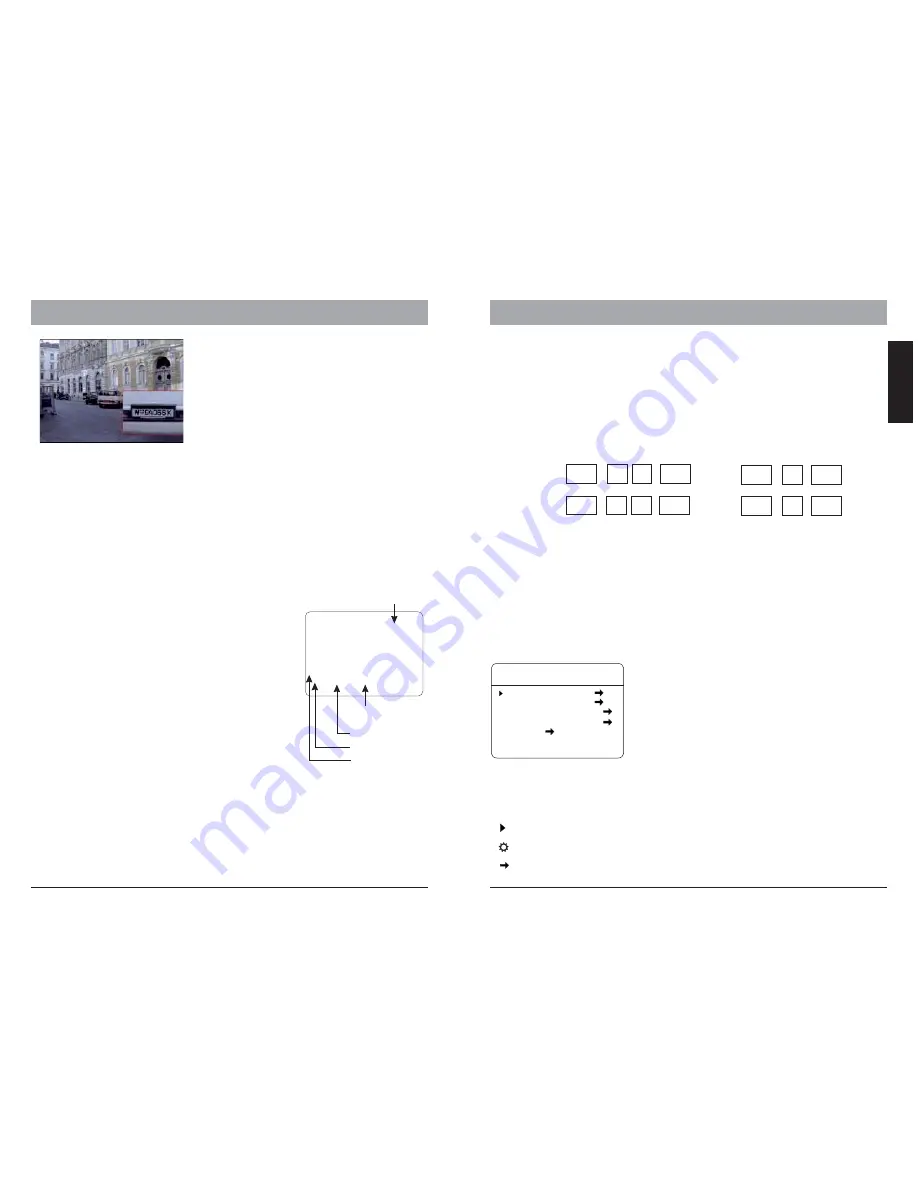
After powering up, the camera will enter the
self-test mode and display the status screen(
as in the picture left).It contains information
about the model and current settings.

- V1.0:
- Protocol:
- Dome address:

- Comm 9600,N,8,1:

Current firmware version

control protocol which currently used

Address ID of speed dome. please refer to the section "Protocol

setup " for details.

current setting of the serial communication interface.

Baud rate. please refer to section "Baud-Rate setup" for details

No parity bit, 8 bit length, 1 stop bit. this setting can not be changed

9600:

N, 8, 1:

Operation  Screen

The intial screen will stay remain on until any user action is being taken. If the power-
up action is set, the initial info wil vanish immediatly.

32.0

CAM TITLE

ZONE-1

285   78

18X

Pan degree

Zoom factor

Tilt degree

Zone description

Temperature

5.OPERATING THE SPEED DOME

PTZ operation

For the surveillance operation, the dome can be controlled from a keyboard device

, Multiplexer or DVR  through RS-485 Interface. Make sure that the cable is connected
and the settings (baud rate, Address ID and protocol) of both keyboard and the dome
are configured correctly. For more description about the PTZ operation, please
refer to the user ’s manual of the keyboard.

Some products may not be available in your country, please contact our distributor for more details

Some products may not be available in your country, please contact our distributor for more details

9

10

ENGLISH

The operation screen can display additional
information.

Temperature: current temperature inside the
speed dome( °C)
Cam title:        User definable camera title
Zone:             Current zone name
Pan deg.:       Pan angle, 0-359°
Tilt deg.:

Tilt angle, 0-90°

Zoom Factor:  Zoom factor

Display of the information can be activate or
deactivate through the OSD menu. please refer to
the system setting for detais.

OSD Menu

How to start the OSD menu

The HSD Series are equipped with new OSD-Menu function. All operation functions and
camera related settings can be changed or modified here. In order to use the OSD function,
a telemetric controller device, such as Keyboard, DVR or other devices with similiar function
is necessarily required. please make sure that the device used is physically connected to the
dome properly, and all connection parameters are set correctly.

To start the OSD Menu, you need to press following key on the keyboard:

With                                                                or

With                                                                or

In case a DVR is used for  the OSD, select “goto preset 95” or 2 X “goto preset 9”. Please
refer to the DVR’s operation manual for more details.

Note that in some certain situations, it is not possible to enter the OSD menu:

1. the dome is running tour
2. performing PTZ operation
3. dome is receiving command other than OSD-request from the keyboard.

please stop the operation and try again.

2 X

2 X

Shot

9

5

Enter

Main menu and navigation

Main Menu

SYSTEM  SETTING
CAMERA SETTING
FUNCTION  SETTING
WINDOW  BLANKING
ALARM
EXIT

After entering the OSD Menu, the screen will show menu
items . Use the controller’ joystick to navigate through
the menu’s main and sub items by moving in the
direction. The angle mark on the beginning of every
items indicates the selection.

UP, DOWN: - Moving between current menu items
- Changing the value in subitems
RIGHT: - Enter the selected menu item
- Confirm the value change and return to
item selection
LEFT: Exit from sub menu

For more inforamtion, please refer to the illustration on
the next page for the OSD menu structure.

Symbols and indicator

Cursor.

Sub item is selected. use up or down to change value

This item has subitem(s)

call

9

5

Enter

call

9

Enter

Shot

9

Enter

Summary of Contents for G65

Page 1: ...USER S MANUAL HD SDI High Speed dome Camera Series ...

Page 2: ...NTIAL AREA IS LIKELY TO CAUSE HARMFUL INTERFERENCE IN WHICH CASE THE USER WILL BE REQUIRED TO CORRECT THE INTERFERENCE AT HIS OWN EXPENSE WARNING THIS IS A CLASS A PRODUCT IN A DOMESTIC ENVIRONMENT THIS PRODUCT MAY CAUSE RADIO INTERFERENCE IN WHICH CASE THE USER MAY BE REQUIRED TO TAKE ADEQUATE MEASURES CAUTION TO REDUCE THE RISK OF ELECTRIC SHOCK DO NOT REMOVE COVER OR BACK NO USER SERVICEABLE PA...

Page 3: ...oids the warranty These will scratch the serface and affect the image qulaity Use the within 20 C to 60 C 4 F to 140 F and a humidity below 90 The input power source is 24V AC 50 60Hz and requires 2500mA outdoor models Do not expose the indoor model of dome camera to water or moisture not try to operate it in wet areas 2 FEATURES The HD SDI High speed dome camera series are designed for in and out...

Page 4: ... least 25mm This appliance has the lightning proof function which can prevent damages caused by high voltage pulse such as lightning strike below 1500 This appliance meets the Ip66 standard for water and dust proof Do not install the in door model for out door application which is not designed with water protection Make sure that the installation is protected from long time water drop or spatter w...

Page 5: ...5 cable The telemetric control of the appliance uses Rs485 serial communication with half duplex transmission technology Depends on the cable typeand baud rate the transmission distance could vary The following table shows max distances based on cable with 0 56mm 24AWG twisted pair 2400 bps 1100 m 700m 400m 4800 bps 1700m 9600 bps 19200 bps Baud Rate Max Distance Due the environmental interference...

Page 6: ...in your country please contact our distributor for more details 7 8 ENGLISH RS 485 Distributor RS 485 cable up to 1000m per channel Termination activated on every end Video Amplifier optional Real time HD SDI DVR Center optional HD SDI Monitor optional HD SDI High Speed Dome Up to 100m coaxial cable Extend connection distance with Video Amplifier Optional bracket accessories The Indoor and Outdoor...

Page 7: ... angle 0 359 Tilt deg Tilt angle 0 90 Zoom Factor Zoom factor Display of the information can be activate or deactivate through the OSD menu please refer to the system setting for detais OSD Menu How to start the OSD menu The HSD Series are equipped with new OSD Menu function All operation functions and camera related settings can be changed or modified here In order to use the OSD function a telem...

Page 8: ... L P A T T E R N S C L E A R A L L T O U R S C L E A R A L L W I N D O W S F A C T O R Y D E F A U L T S R E S T A R T B A C K E X I T T O U R T O U R R U N T O U R B A C K E X I T NUMBER 1 EDIT TOUR CLEAR TOUR W I N D O W N U M B E R 0 1 E D I T W I N D O W E N A B L E W I N D O W O N C L E A R W I N D O W B A C K E X I T W I N D O W B L A N K I N G ALARM NUMBER 001 ALARN ACTION NONE ACTIVATE AUX...

Page 9: ... BACK EXIT ADVANCE SETTING EIS ENABLED N A PRESET FREEZEN OFF AUTO FOCUS OFF DEFOGGER 015C HEAD UP OFF BACK EXIT CAMERA SETTING In camera setting menu you can setup camera module related settings please note that depends on module s capability some function may not available please contact your local sales representative for detailed information defines the speed when performing zoom function Acti...

Page 10: ...es PRESETS PRESET NUMBER 001 S E T P R E S E T S H O W P R E S E T C L E A R P R E S E T AUTO TRACKING ON E D I T P R E S E T L A B E L BACK EXIT PRESETS PRESET NUMBER SET PRESET SHOW PRESET G65 70 Series supports up to 128 presets The number can be selected from 0 to 128 Defining the preset points directly in OSD by entering this menu item and move the PTZ press IRIS OPEN key on the keyboard to s...

Page 11: ...ice to enter the preset point selection Move the joystick with up and down to select the preset points by number and save the setting with IRIS OPEN key with IRIS CLOSE key you can move to the previous selection If a select point has the value 0 all the following presets points will be ignored Starts the tour and exit the OSD menu EDIT TOUR TOUR DWELL 001 00 00 00 00 00 00 00 00 00 00 00 00 00 00 ...

Page 12: ...0 9600 bps 0 1 19200 bps 1 1 SW 1 represent the domes address in binary form please refer to the list on next page for reference SW 2 Used for protocol settting and baud rate DIP 1 to 6 Protocol setting DIP 7 and 8 Baud rate setting Protocol DIP 1 2 3 4 5 6 VIDO B02 0 0 1 1 0 0 DIAMOND 1 0 0 1 0 0 HUNDA 1 0 1 1 0 0 KALATEL 0 1 0 1 0 0 LILIN 1 1 0 1 0 0 MOLYNX 0 0 1 0 0 0 PANASONIC 1 1 1 0 0 0 PELC...

Page 13: ...1 1 1 0 0 0 0 0 41 1 0 0 1 0 1 0 0 ID ID 0 0 0 0 0 0 0 0 0 1 0 0 0 1 0 0 34 Bit 1 2 3 4 5 6 7 8 Bit 1 2 3 4 5 6 7 8 0 0 1 0 0 0 1 0 0 1 1 0 0 1 1 0 1 0 1 0 0 0 1 0 1 1 1 0 0 1 1 0 0 1 1 0 0 0 1 0 0 0 0 1 0 1 1 0 1 1 1 0 0 0 1 0 1 0 0 1 0 1 1 0 0 0 0 1 0 0 1 0 0 1 0 1 0 1 1 0 1 0 0 1 0 0 1 0 1 1 0 1 0 1 1 0 0 1 0 1 0 0 1 0 0 0 1 1 0 1 1 0 1 1 0 1 0 0 1 0 1 0 1 1 0 1 1 0 0 0 1 1 0 0 1 0 0 1 1 1 0 1 ...

Page 14: ...179 170 180 181 182 183 184 185 186 187 188 189 190 191 193 178 194 195 196 197 198 199 200 201 202 203 192 Switchnumber Sw1 136 137 138 139 140 141 142 143 145 146 147 148 149 150 151 152 153 154 155 156 157 159 144 160 161 162 163 164 165 166 167 168 169 158 Switchnumber Sw1 Bit 1 2 3 4 5 6 7 8 0 0 1 1 0 0 1 1 0 1 1 1 0 1 1 1 1 0 1 1 0 0 1 1 1 1 1 1 0 1 1 1 0 1 1 1 0 0 1 1 0 0 0 0 1 1 1 1 1 1 1 ...

Reviews: