Sony G65 User Manual Download Page 10

OSD - Preset, Scan

6.OSD - Patterns, Tours
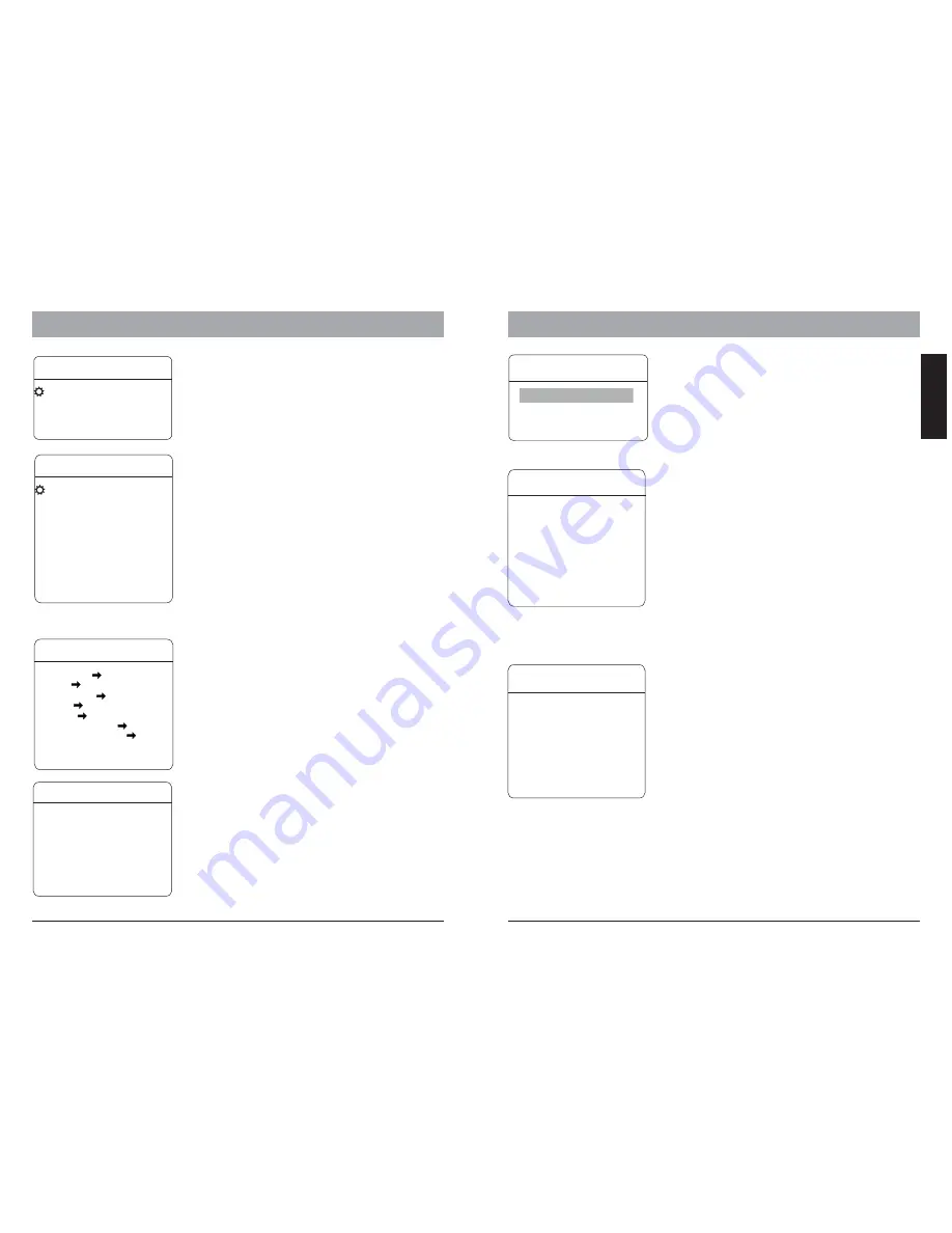
ADVANCE  SETTING

2

AE  MODE

AUTO

SHUTTER

N/A

IRIS

N/A

BRIGHT

N/A

WB  MODE

AUTO

R GAIN

N/A

B GAIN

N/A

HI-RESOLUTION          OFF
BACK
EXIT

ADVANCE SETTING 2

AE MODE:

WB MODE:

ALC, PLC:

Under the advanced setting, you can make
improvements to image quality due to different
environmental conditions.

Auto Exposure mode. Depends on the light

condition in the surveillance area, you can set the AE in
different modes and adjust the parameters, such as
shutter speed, iris factor and brightness for the best
image quality.

White balance mode, a image improvement

based on DSP processing. you can also adjust the Red-
Gain or Blue-Gain to change the color tone.

Average and Peak Level Control,

additional setting to WB function. only avialble with
dedicated camera modules.

FUNCTION SETTING

In function setting menu, you can define and activate
different PTZ funcitons, such as preset points, auto
scan, tours and Pattern. Presets and tour functions
can also be set or activated directly from keyboard
device without OSD. Please refer to the keyboard’s
manual for  operation details.

Some products may not be available in your country, please contact our distributor for more details

Some products may not be available in your country, please contact our distributor for more details

15

ENGLISH

FUNCTION  SETTING

PRESETS
SCAN
PATTERNS
TOUR
ZONES
TIME RUNNING
AUTO-TRACKING
BACK
EXIT

ADVANCE  SETTING

1

PS SCAN                          ON
STABLE ZOOM                ON
DNR                                   00
BACK
EXIT

ADVANCE SETTING 1

These function are o

Activate Progressive Scan, can be combine

on the WDR mode.

This function is performing correction

using the Image Stabilizer function in accordance with
the zoom ratio, and smoothly zooming up to
approximately ×40 using a combination of the optical
zoom and digital zoom.

Set the 2D/3D

igital

oise

eduction.

PS SCAN:

STABLE ZOOM:

DNR:

D

N

R

nly available with the E-Serie

camera modules

PRESETS

P R E S E T N U M B E R

0 0 1

S E T P R E S E T
S H O W P R E S E T
C L E A R P R E S E T
A U TO - T R A C K I N G

O N

E D I T P R E S E T L A B E L
B A C K
E X I T

PRESETS:

PRESET NUMBER:

SET PRESET:

SHOW PRESET:

G65-70 Series supports up to

128 presets. The number can be selected from 0 to
128.

Defining the preset points directly in

OSD by entering this menu item and move the PTZ.
press IRIS-OPEN key on the keyboard to save. If the
preset is pointed within digital zoom, it will
automatically go back to max. optical zoom range in
order to provide the best image.

Moves to current preset point

PATTERNS

Pattern

Pattern records the user’s operation steps on
performing PTZ control and stores as a track. The
Speed Dome can record up to 4 tracks with max.
180 sec. each.

PATTERN  NUMBER:

PROGRAM  PATTERN:

RUN  PATTERN:

CLEAR  PATTERN:

EDIT  PATTERN  LABEL :

Selects the pattern number,

from 1 to 4

Starts recording the pattern

when selected. you can perfome PTZ movement for
recording and shall not exceed 180 sec. Press IRIS-
OPEN to save the track.

Starts the current pattern

Delete curretn pattern.

Sets the name for current

pattern.

PATTERN  NUMBER    1
PROGRAM  PATTERN
RUN  PATTERN
CLEAR  PATTERN
EDIT PATTERN  LABEL
BACK
EXIT

Clear the current preset

Start Auto Tracking, if the preset

is called.

For the current preset, you

can define a name which will be shon on the
operation screen once the preset is called. please
choose the preset number at first. The avaialbe
characters are: 0-9, A-Z, <,>,. and space.

CLEAR PRESET:

AUTO-TRACKING:

EDIT PRESET LABEL:

EDIT  PRESET  LABEL

LABEL
BACK
EXIT

ROOM 1

SCAN

SCAN NUMBER:

SCAN SPEED:

SET LEFT LIMIT:
SET RIGHT LIMIT:
CLEAR SCAN:
RUN SCAN:
EDIT SCAN LABEL:

The SCAN function moves the PTZ between 2-
predefined points in constant speed.The
following parameters can be set:

The Speed Dome

cruising speed between the

points.

defines the left point.

defines the right point

Delete the scan setting

starting the scan function

set the name for the scan

supports up to 4

scan.

SCAN

SCAN NUMBER   01
SCAN  SPEED      63
SET LEFT LIMIT
SET RIGHT LIMIT

RUN  SCAN
EDIT SCAN  LABEL
BACK
EXIT

CLEAR  SCAN

16

Summary of Contents for G65

Page 1: ...USER S MANUAL HD SDI High Speed dome Camera Series ...

Page 2: ...NTIAL AREA IS LIKELY TO CAUSE HARMFUL INTERFERENCE IN WHICH CASE THE USER WILL BE REQUIRED TO CORRECT THE INTERFERENCE AT HIS OWN EXPENSE WARNING THIS IS A CLASS A PRODUCT IN A DOMESTIC ENVIRONMENT THIS PRODUCT MAY CAUSE RADIO INTERFERENCE IN WHICH CASE THE USER MAY BE REQUIRED TO TAKE ADEQUATE MEASURES CAUTION TO REDUCE THE RISK OF ELECTRIC SHOCK DO NOT REMOVE COVER OR BACK NO USER SERVICEABLE PA...

Page 3: ...oids the warranty These will scratch the serface and affect the image qulaity Use the within 20 C to 60 C 4 F to 140 F and a humidity below 90 The input power source is 24V AC 50 60Hz and requires 2500mA outdoor models Do not expose the indoor model of dome camera to water or moisture not try to operate it in wet areas 2 FEATURES The HD SDI High speed dome camera series are designed for in and out...

Page 4: ... least 25mm This appliance has the lightning proof function which can prevent damages caused by high voltage pulse such as lightning strike below 1500 This appliance meets the Ip66 standard for water and dust proof Do not install the in door model for out door application which is not designed with water protection Make sure that the installation is protected from long time water drop or spatter w...

Page 5: ...5 cable The telemetric control of the appliance uses Rs485 serial communication with half duplex transmission technology Depends on the cable typeand baud rate the transmission distance could vary The following table shows max distances based on cable with 0 56mm 24AWG twisted pair 2400 bps 1100 m 700m 400m 4800 bps 1700m 9600 bps 19200 bps Baud Rate Max Distance Due the environmental interference...

Page 6: ...in your country please contact our distributor for more details 7 8 ENGLISH RS 485 Distributor RS 485 cable up to 1000m per channel Termination activated on every end Video Amplifier optional Real time HD SDI DVR Center optional HD SDI Monitor optional HD SDI High Speed Dome Up to 100m coaxial cable Extend connection distance with Video Amplifier Optional bracket accessories The Indoor and Outdoor...

Page 7: ... angle 0 359 Tilt deg Tilt angle 0 90 Zoom Factor Zoom factor Display of the information can be activate or deactivate through the OSD menu please refer to the system setting for detais OSD Menu How to start the OSD menu The HSD Series are equipped with new OSD Menu function All operation functions and camera related settings can be changed or modified here In order to use the OSD function a telem...

Page 8: ... L P A T T E R N S C L E A R A L L T O U R S C L E A R A L L W I N D O W S F A C T O R Y D E F A U L T S R E S T A R T B A C K E X I T T O U R T O U R R U N T O U R B A C K E X I T NUMBER 1 EDIT TOUR CLEAR TOUR W I N D O W N U M B E R 0 1 E D I T W I N D O W E N A B L E W I N D O W O N C L E A R W I N D O W B A C K E X I T W I N D O W B L A N K I N G ALARM NUMBER 001 ALARN ACTION NONE ACTIVATE AUX...

Page 9: ... BACK EXIT ADVANCE SETTING EIS ENABLED N A PRESET FREEZEN OFF AUTO FOCUS OFF DEFOGGER 015C HEAD UP OFF BACK EXIT CAMERA SETTING In camera setting menu you can setup camera module related settings please note that depends on module s capability some function may not available please contact your local sales representative for detailed information defines the speed when performing zoom function Acti...

Page 10: ...es PRESETS PRESET NUMBER 001 S E T P R E S E T S H O W P R E S E T C L E A R P R E S E T AUTO TRACKING ON E D I T P R E S E T L A B E L BACK EXIT PRESETS PRESET NUMBER SET PRESET SHOW PRESET G65 70 Series supports up to 128 presets The number can be selected from 0 to 128 Defining the preset points directly in OSD by entering this menu item and move the PTZ press IRIS OPEN key on the keyboard to s...

Page 11: ...ice to enter the preset point selection Move the joystick with up and down to select the preset points by number and save the setting with IRIS OPEN key with IRIS CLOSE key you can move to the previous selection If a select point has the value 0 all the following presets points will be ignored Starts the tour and exit the OSD menu EDIT TOUR TOUR DWELL 001 00 00 00 00 00 00 00 00 00 00 00 00 00 00 ...

Page 12: ...0 9600 bps 0 1 19200 bps 1 1 SW 1 represent the domes address in binary form please refer to the list on next page for reference SW 2 Used for protocol settting and baud rate DIP 1 to 6 Protocol setting DIP 7 and 8 Baud rate setting Protocol DIP 1 2 3 4 5 6 VIDO B02 0 0 1 1 0 0 DIAMOND 1 0 0 1 0 0 HUNDA 1 0 1 1 0 0 KALATEL 0 1 0 1 0 0 LILIN 1 1 0 1 0 0 MOLYNX 0 0 1 0 0 0 PANASONIC 1 1 1 0 0 0 PELC...

Page 13: ...1 1 1 0 0 0 0 0 41 1 0 0 1 0 1 0 0 ID ID 0 0 0 0 0 0 0 0 0 1 0 0 0 1 0 0 34 Bit 1 2 3 4 5 6 7 8 Bit 1 2 3 4 5 6 7 8 0 0 1 0 0 0 1 0 0 1 1 0 0 1 1 0 1 0 1 0 0 0 1 0 1 1 1 0 0 1 1 0 0 1 1 0 0 0 1 0 0 0 0 1 0 1 1 0 1 1 1 0 0 0 1 0 1 0 0 1 0 1 1 0 0 0 0 1 0 0 1 0 0 1 0 1 0 1 1 0 1 0 0 1 0 0 1 0 1 1 0 1 0 1 1 0 0 1 0 1 0 0 1 0 0 0 1 1 0 1 1 0 1 1 0 1 0 0 1 0 1 0 1 1 0 1 1 0 0 0 1 1 0 0 1 0 0 1 1 1 0 1 ...

Page 14: ...179 170 180 181 182 183 184 185 186 187 188 189 190 191 193 178 194 195 196 197 198 199 200 201 202 203 192 Switchnumber Sw1 136 137 138 139 140 141 142 143 145 146 147 148 149 150 151 152 153 154 155 156 157 159 144 160 161 162 163 164 165 166 167 168 169 158 Switchnumber Sw1 Bit 1 2 3 4 5 6 7 8 0 0 1 1 0 0 1 1 0 1 1 1 0 1 1 1 1 0 1 1 0 0 1 1 1 1 1 1 0 1 1 1 0 1 1 1 0 0 1 1 0 0 0 0 1 1 1 1 1 1 1 ...

Reviews: