background image

29

Items Related to Network 
(NETWORK submenu)


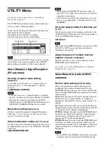
The NETWORK submenu can be configured after the 
NETWORK function internal processing has completed 
after power is turned on. When ready, a > mark is 
displayed beside the name of each function.

Receiver name setting 

(RECEIVER NAME)

Enter a receiver name of up to 16 characters. The entry 
method is the same as described in 

“Using Password 

Mode (PASSWORD)” (page 18)

.

When the receiver is already named, selecting this item 
displays the receiver name.

Network mode setting 

(NETWORK MODE)

Set the signal transmitted from the LAN connector on the 
network.

SWITCHED:

 Transmits the same signal from both of the 

LAN connectors. Signals for the Dante primary network 
and for communication between DWX devices are 
transmitted from both the PRIMARY connector and 
SECONDARY connector. Select this when using a single 
network, and when daisy-chained with other receivers.

REDUNDANT:

 Enable the Dante redundancy function. 

Signals for the Dante primary network and for 
communication between DWX devices are transmitted 
from the PRIMARY connector, and signals for the Dante 
secondary network are transmitted from the 
SECONDARY connector. Select this when you want to 
ensure redundancy of Dante audio using two networks.

SEPARATE:

 Separate the Dante network and the 

network for communication between DWX devices. 
Signals for the Dante network are transmitted from the 
PRIMARY connector, and signals for communication 
between DWX devices are transmitted from the 
SECONDARY connector.

Dante device name setting 

(DANTE ID)

Sets the device name for identifying a device on the Dante 
network.

ID MODE

YAMAHA ID:

 Select this when connecting a Yamaha 

brand device with the unit.

FREE ID:

 Set an arbitrary ID. The entry method is the 

same as described in 

“Using Password Mode 

(PASSWORD)” (page 18)

.

ID

Displays the configured ID.

IP address setting for communication 
between DWX devices 

(RECEIVER IP)

Enter the IP address to use for communication between 
DWX devices.

IP MODE

AUTO:

 Assign network settings automatically.

MANUAL:

 Configure network settings manually.

IP ADDRESS

Set the IP address when IP MODE is set to MANUAL. 
The assigned IP address is displayed when set to AUTO.

SUBNET MASK

Set the subnet mask when IP MODE is set to MANUAL. 
The assigned subnet mask is displayed when set to 
AUTO.

IP address setting for Dante Primary 
communication 

(DANTE MAIN IP)

Sets the IP address to use for Dante Primary 
communication.
The settings are the same as those described in “IP 
address setting for communication between DWX 
devices (RECEIVER IP).”

IP address setting for Dante Secondary 
communication 

(DANTE SUB IP)

Sets the IP address to use for Dante Secondary 
communication.
The settings are the same as those described in “IP 
address setting for communication between DWX 
devices (RECEIVER IP).”


DANTE SUB IP is enabled only when NETWORK 
MODE is set to REDUNDANT.

Items Related to Alerts (ALERT 
FUNCTION submenu)

Low signal input level 

(RF LOW)

Specifies whether to display a warning via the ALERT 
indicator when the signal input level detected is low.

ON/OFF

Excess signal input level

 (RF OVER)

Specifies whether to display a warning via the ALERT 
indicator when the signal input level detected is 
excessive.

ON/OFF

Low receiving signal quality 

(QL LOW)

Specifies whether to display a warning via the ALERT 
indicator when the quality of the received signal is low.

ON/OFF


Specifies the level at which the quality of the received 
signal is detected as low.

Note

Note

Note

Summary of Contents for DWR-R03D

Page 1: ...Digital Wireless Receiver Operating Instructions DWR R03D 4 739 826 03 1 2018 Sony Corporation ...

Page 2: ...o Output Level Setting MAIN OUT LEVEL 23 Ground Lift Setting GROUND LIFT 23 Audio Output Setting AF OUTPUT 23 Transmitter Search Function SEARCH TX 23 Label Function CHANNEL LABEL 23 TRANSMITTER Transmitter Virtual Menu 24 Display of the Transmitter Name NAME 24 Display of the Power Save Setting POWER SAVE 24 Display of the Transmission Power Setting RF POWER 24 Display of Audio Input Level INPUT ...

Page 3: ...TT 32 Low cut Filter Setting LCF 32 48 V Power Setting 48V 32 Resetting Accumulated Transmitter Use Time TIME 32 Audio codec mode setting CODEC MODE 32 Internal Signal Setting INTERNAL SG 32 Lock Function LOCK 32 Display Method for Remaining Battery Capacity BATTERY REMAIN 32 Block Diagram 34 When the ALERT Indicator Lights 35 Error Messages 36 Troubleshooting 37 Important Notes on Operation 38 No...

Page 4: ...such cases Dante audio networking support IP transmission of multi channel audio and redundancy is supported via the two Dante ports Monitoring the audio of a separate receiver is also possible without having to switch the connected headphones Stable RF transmissions Stable RF transmission is achieved via the X Dimension Diversity reception system and RF lines with high dynamic range The unit supp...

Page 5: ...e connected to establish an antenna cascade allowing operation with up to 16 channels without the use of an antenna divider Using a WD 850 UHF Antenna Divider not supplied allows you to configure systems that exceed 16 channels When 4 ANTENNA is selected using the DIVERSITY setting all four antenna connectors become input connectors and cascade connection is not possible If you want to use two or ...

Page 6: ...n turning off the main power supply b UTILITY UTILITY menu button Press to display UTILITY menu This button lights up brightly during UTILITY menu operation c VOLUME monitor volume control Rotate to control the monitor volume of the selected channel d PHONES headphones terminal Connect the headphones here 1 2 1 2 4 3 Display page 7 Controls page 8 ...

Page 7: ...DIGITAL OUT connectors INT Output signal is in sync with the internal clock EXT Output signal is in sync with the signal input from the WORD SYNC IN connector f AF PEAK audio signal peak indicator Lights up green when the audio signal exceeding reference level is input to the transmitter Lights up red when the audio signal exceeding 3 dBFs is input to the A D converter on the transmitter g Audio l...

Page 8: ...on the input level o Antenna selection indicator Indicates the antenna currently selected by the diversity function 2 Controls The control areas for channel 1 and channel 2 are identical a MONITOR monitor output button Press to monitor the output of the selected receiver channel via the headphones The UTILITY AUDIO MONITOR MODE setting allows you to output only the selected receiver channel output...

Page 9: ...nector BNC R These connectors output a digital audio signal in AES3 format Connect the digital input connector of mixer amplifier or other equipment e ANTENNA a b IN antenna a b input connectors BNC R Connect an optional UHF antenna e g AN 820A and the supplied whip antenna to these connectors When an antenna is connected this connector supplies 9 V or 12 V DC power to the booster incorporated in ...

Page 10: ...units in a cascade connection install the units as shown in the following or mount them on a rack h ANTENNA a b OUT antenna a b output or ANTENNA c d IN antenna c d input connectors BNC R Connect additional DWR R03D units to either ANTENNA a b OUT connectors and create cascade connections of up to eight units You can also select the 4 channel diversity reception mode via menu operations to use the...

Page 11: ...use the wireless remote control function where it will be within range of the audio signal from the transmitter When using Wireless Studio When not using Wireless Studio Using the Supplied Antennas To maximize the reception performance of this unit we recommend using optional AN 820A or AN 01 UHF antennas For narrow service areas however you can also use the supplied whip antennas When using the s...

Page 12: ... supplied whip antennas to the ANTENNA a b IN connectors on the rear panel Connection Example of Word Clock and Audio For digital audio output to be performed correctly it is necessary to connect a device incorporating a sampling rate converter to the DIGITAL OUT connector of the receiver or input a master word clock signal to the WORD SYNC IN connector of the receiver and perform synchronization ...

Page 13: ...ing signals in a wide band of frequencies Set the band block before setting the frequency band group channel Set the band block BAND BLOCK as follows This function cannot be used when the AUTO FREQ CHANGE function or CHANNEL COORDINATE function is enabled The controls for channel 1 are used in the following illustration for explanation purposes 1 Press the UTILITY button to select the UTILITY menu...

Page 14: ...nnel CH configured on the receiver is a channel for which use with the wireless remote control function is restricted on the transmitter side the UNMATCH screen appears In such cases change the receiving channel on the receiver If you want to use the restricted channel set REMOTE to OFF in the transmitter s menu to release the channel restriction and manually configure the transmitter s channel If...

Page 15: ...indication and then press the dial A message START SCAN appears 3 Rotate the jog dial to select YES and then press the dial Scanning starts Empty channels within the specified channel group GP are searched When scanning finishes detected empty channels are listed in the order with less interference 4 Rotate the jog dial to select the channel that you want to use and then press the dial When the Cr...

Page 16: ...e the jog dial to move the cursor to the AUTO indication and then press the dial The group names and corresponding empty channels in the searched BAND are displayed 2 Rotate the jog dial to select the group that you want to use and then press the dial Channels are assigned to tuner 1 and turner 2 in order from the DWR R03D unit with the lowest IP address If there are insufficient empty channels in...

Page 17: ...equency and there is no assignable frequency available preventing the frequency switching the CLIENT icon flashes If no RF signal is transmitted from a transmitter paired with a client for example it is turned off or in sleep mode the host may assign the frequency used by that transmitter to another client When using this function a total of up to three network connected computers with Wireless St...

Page 18: ...nstructions supplied with the transmitter 2 Preparing the receiver this unit 1 In the RECEIVER menu rotate the jog dial to move the cursor to ENCRYPTION indication and then press the dial 2 Rotate the jog dial to select SECURE KEY or AES256 and then press the dial If the transmitter does not support AES256 mode select SECURE KEY For details on the transmitter s encrypted transmission function refe...

Page 19: ... codec mode that uses additional signal processing to suppress noise caused by unexpected pulse interference MODE4 Audio codec mode that prioritizes audio quality for faithful reproduction while maintaining transmission stability and low delay time The audio delay time of the transmitted received signal in each mode will vary depending on the transmitter usage environment For details see Audio Cod...

Page 20: ...s meter indications network settings and settings for the organic light emitting diode display The UTILITY menu settings apply to receiver channel 1 and 2 Menu hierarchy RECEIVER menu BAND GP CH ACTIVE CH SCAN CLEAR CH SCAN SPECTRUM ANALYZER ENCRYPTION CODEC MODE MAIN OUT LEVEL GROUND LIFT AF OUTPUT SEARCH TX CHANNEL LABEL TRANSMITTER menu NAME POWER SAVE RF POWER INPUT LEVEL ATT LCF 48V TIME INTE...

Page 21: ...or details see Menu Structure and Hierarchy page 20 3 Rotate the jog dial to change the setting 4 Press the jog dial to enter the setting NETWORK RECEIVER NAME NETWORK MODE DANTE ID RECEIVER IP DANTE MAIN IP DANTE SUB IP ALERT FUNCTION RF LOW RF OVER QL LOW AF PEAK TX BATTERY LOW ENCRYPTION UNMATCH EXTERNAL WORD SYNC UNLOCK CODEC MODE UNMATCH QL ALERT SENS DISPLAY BRIGHTNESS DIMMER MODE SETTING LO...

Page 22: ... Transmission Function ENCRYPTION Set the parameters for the encrypted transmission function SECURE KEY Sets the encryption key compatibility with first and second generation DWX series devices AES256 Sets the AES256 encryption key method PASSWORD Sets the password method OFF The encrypted transmission function is not used For details see Using the Encrypted Transmission Function page 18 Audio Cod...

Page 23: ...p display alternates between displaying MUTING and the transmitter name Transmitter Search Function SEARCH TX This function quickly searches for a transmitter communicating on the same frequency as the unit When a transmitter is found it is indicated by the transmitter display flashing or other indication If the transmitter does not support the receiver search function the transmitter will not res...

Page 24: ...ting RF POWER The transmission power setting of the transmitter from which transmission is currently being received is displayed Display of Audio Input Level INPUT LEVEL The audio input level setting of the transmitter from which transmission is currently being received is displayed Display of the Attenuator ATT The attenuator setting of the transmitter is displayed Display of the Low cut Filter S...

Page 25: ...ails on transmitter operations refer to the operating instructions supplied with the transmitter 3 Rotate the jog dial to select YES and then press the dial The receiver starts searching for transmitters and then displays the names of transmitters with which pairing is possible During the search pressing any operation key on the receiver will cancel pairing mode 4 Rotate the jog dial to select the...

Page 26: ...ettings see Changing the Settings on the Transmitter page 31 Cancelling the Cross Remote In the RF REMOTE menu select RF REMOTE and then select OFF Notes on the Cross Remote The wireless remote control function on the receiver uses the 2 4 GHz band and may thus be subject to interference from other devices When pairing fails PAIRING FAIL is displayed carry out pairing again Successful communicatio...

Page 27: ...SITY DC power supply setting for antennas ANT DC OUT Sets the power supply for the antennas connected to the ANTENNA a b c d IN connectors This setting applies to all of the ANTENNA IN connectors OFF 9V 12V When connecting DWR R03D units in cascade set ANT DC OUT to OFF on any unit that is not directly connected to the antenna Adjust frequency of multiple receivers together CHANNEL COORDINATE This...

Page 28: ... a device such as mixer or delay processor set this function to OFF AF peak level hold duration setting AF PEAK HOLD Set the peak level hold condition for the audio level meter that appears on the top display and other situations 2SEC Hold the audio level meter s peak display for 2 seconds HOLD Hold the audio level meter s peak display until it is released Releasing the peak display You can releas...

Page 29: ... this when connecting a Yamaha brand device with the unit FREE ID Set an arbitrary ID The entry method is the same as described in Using Password Mode PASSWORD page 18 ID Displays the configured ID IP address setting for communication between DWX devices RECEIVER IP Enter the IP address to use for communication between DWX devices IP MODE AUTO Assign network settings automatically MANUAL Configure...

Page 30: ...s If QL LOW is set to OFF in the ALERT FUNCTION submenu the ALERT indicator will not light even is the quality of the received signal is low For details see Low receiving signal quality QL LOW page 29 Items Related to Display DISPLAY submenu Setting the brightness of the display BRIGHTNESS Ten levels of brightness can be selected for the organic light emitting diode display The selectable settings...

Page 31: ...hanging the settings be sure to set pairing configurations in the RF REMOTE menu and enable the wireless remote control function by setting RF REMOTE to ON The following shows the US model display Frequency band setting BAND Set this setting in the BAND screen of the RECEIVER menu For details see Selecting the Frequency Band page 14 Group channel Setting GP CH Only this setting is set through the ...

Page 32: ...ange the attenuator value when the audio input level setting of the transmitter is set to MIC The attenuator values that can be selected depend on the transmitter function Low cut Filter Setting LCF The low cut filter setting of the transmitter can be changed The frequency selection depends on the transmitter function 48 V Power Setting 48V The 48 V power on the transmitter can be turned on or off...

Page 33: ...unit To display the cumulative usage time of the unit set to other than TIME When TIME and PERCENT are selected the cumulative usage time cannot be reset using the wireless remote control function The displayed value is a guide and may not be accurate depending on the usage conditions and environment ...

Page 34: ... Divider Digital wireless tuner 1 Digital wireless tuner 2 Digital Signal Processor 75 Ω terminator Divider Cascade output 2 antenna mode Cascade output 2 antenna mode 4 antenna mode 4 antenna mode RF switch RF switch ...

Page 35: ...lity of the received signal is determined to be low The RF indicator is lit in orange The signal input level of the antenna is 87 dBµ 0 dBµ 1 µVEMF or higher Multi channel synchronous operation may be affected Try one of the following Try using the transmitter located away from the antenna Increase the ANT ATT a b c d setting value of the receiver If the ANT ATT a b c d setting value is increased ...

Page 36: ...HONES terminal exceeds the maximum allowable current or the terminal has short circuited ANTENNA OVER CURRENT DC outputs from the ANTENNA IN connectors exceed the maximum allowable current or the connectors have short circuited CPU EEP ROM NG The data of the CPU EEP ROM is not correct RF EEP ROM NG The data of the RF EEP ROM is not correct ...

Page 37: ... channel whose RF indicator on the receiver does not light up and then set that same channel on the transmitter When two or more transmitters are being used change to another channel group that is unaffected by jamming radio waves When doing this the clear channel scan function is useful page 15 Two or more transmitters are set to the same channel It is not possible to use two or more transmitters...

Page 38: ... as the connectors with a dry soft cloth soon after use Lengthy use of the receiver in such places or not cleaning it after its use in such places may shorten its life Clean the surface and the connectors of the receiver with a dry soft cloth Never use thinner benzene alcohol or any other chemicals since these may mar the finish Transmitter Software Version If the software version is not suitable ...

Page 39: ...ess at bit error rate 1 10 5 no decline in S N ratio Antenna section Antenna Connector 2 DIVERSITY Input BNC R 50 Ω 2 Cascade output BNC R 50 Ω 2 4 DIVERSITY Input BNC R 50 Ω 4 Supply Voltage for Booster 0 V 9 V 12 V Attenuator 0 dB 3 dB 6 dB 9 dB 12 dB Audio section Dynamic Range 106 dB or more A weighted Distortion T H D MODE1 MODE2 MODE4 0 03 or less MODE3 0 3 or less Audio Delay MODE1 1 9 ms a...

Page 40: ...wer cord Part No 1 912 652 1x Sony 1 Plug holder 2 Foot 4 Warranty card US models only 1 Before Using This Unit 3 Operating Instructions CD ROM 1 Open source software technical information CD ROM 1 Design and specifications are subject to change without notice Trademarks All system names product names and company names described in this document are registered trademarks or trademarks of their res...

Page 41: ...565 875 MHz TV30 33 566 125 589 875 MHz TV34 36 590 125 607 875 MHz TV37 Not available TV38 614 125 615 875 MHz Model No BAND BLOCK Frequency band Frequency Group channel factory setting W TV21 29 TV21 23 470 025 494 000 MHz 00 2101 470 125MHz TV24 26 494 025 518 000 MHz TV27 29 518 025 542 000 MHz TV30 41 TV30 32 542 025 566 000 MHz TV33 35 566 025 590 000 MHz TV36 38 590 025 614 000 MHz TV38 40 ...

Page 42: ...Sony Corporation ...

Reviews: