


1-4
18
Hookups
Hooking Up the Player
Follow Steps 1 to 4 to hook up and adjust the settings of the player.
Before you start, disconnect the power cords, check that you have all of the supplied accessories,
and insert the batteries into the remote (page 15).
Notes
• Plug cords securely to prevent unwanted noise.
• Refer to the instructions supplied with the components to be connected.
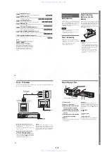
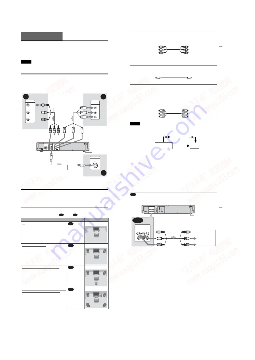
Step 1: Connecting the Video Cords
Connect this player to your TV monitor, projector, or AV amplifier (receiver) using a video cord.
Select one of the patterns
A
through
C
, according to the input jack on your TV monitor,
projector, or AV amplifier (receiver).
B
A
C
INPUT
S VIDEO
P
R
P
B
Y
COMPONENT
VIDEO IN
VIDEO
AUDIO
INPUT
L
R
PCM/DTS/DOLBY DIGITAL
COAXIAL
OPTICAL
DIGITAL OUT
R
1
2
L
AUDIO
VIDEO
LINE OUT
1
2
S VIDEO
OUT
COMPONENT VIDEO OUT
Y
SCAN SELECT
SELECTABLE
INTERLACE
PROGRESSIVE
PB
PR
Audio/video
cord
(supplied)
l
: Signal flow
Component
video cord
(not supplied)
(yellow)
TV, projector or AV
amplifier (receiver)
CD/DVD player
TV, projector or AV
amplifier (receiver)
(green)
S VIDEO cord
(not supplied)
TV, projector or AV
amplifier (receiver)
(red)
(blue)
(yellow)
(green)
(blue)
(red)
to LINE OUT (VIDEO)1 or 2
to COMPONENT
VIDEO OUT
to S VIDEO OUT 1 or 2
19
H
ook
up
s
A
If you are connecting to a video input jack
Connect the yellow plug of the audio/video cord (supplied) to the yellow (video) jacks. You will
enjoy standard quality images.
Use the red and white plugs to connect to the audio input jacks (page 21). (Do this if you are
connecting to a TV only.)
B
If you are connecting to an S VIDEO input jack
Connect an S VIDEO cord (not supplied). You will enjoy high quality images.
C
If you are connecting to a monitor, projector, or AV amplifier (receiver)
having component video input jacks (Y, P
B
, P
R
)
Connect the component via the COMPONENT VIDEO OUT jacks using a component video
cord (not supplied) or three video cords (not supplied) of the same kind and length. You will
enjoy accurate color reproduction and high quality images. If your TV accepts progressive
(480p) format signals, you must use this connection and set “COMPONENT OUT” to
“PROGRESSIVE” in “SCREEN SETUP” (page 65).
Notes
• Do not connect the player to a VCR. If you pass the player signals via the VCR, you may not receive a clear
image on the TV screen.
• Consumers should note that not all high definition television sets are fully compatible with this product and
may cause artifacts to be displayed in the picture. In the case of 480 progressive scan picture problems, it
is recommended that you switch the connection to the standard definition output. If there are questions
regarding your Sony TV set’s compatibility with this model 480p DVD player, please contact our customer
service center.
Yellow (Video)
White (L)
Red (R)
Yellow (Video)
White (L)
Red (R)
Green
Blue
Red
Green
Blue
Red
VCR
CD/DVD player
TV
Connect
directly
20
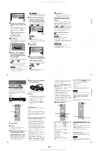
Step 2: Connecting the Audio Cords
Refer to the chart below to select the connection that best suits your system. Be sure to also read
the instructions for the components you wish to connect.
Select a connection
Select one of the following connections,
through
.
* Manufactured under license from Dolby
Laboratories. “Dolby,” “Pro Logic,” and the
double-D symbol are trademarks of Dolby
Laboratories.
** “DTS” and “DTS Digital Out” are trademarks
of Digital Theater Systems, Inc.
Components to be connected
Connection
Your setup
TV
• Surround effects: TVS DYNAMIC (page 50),
TVS WIDE (page 50)
(page 21)
example
Stereo amplifier (receiver) and two speakers
• Surround effects: TVS STANDARD (page 50)
or
(page 22)
example
AV amplifier (receiver) having a Dolby
Surround (Pro Logic) decoder and 3 to 6
speakers
• Surround effects: Dolby Surround (Pro Logic)
(page 23)
example
AV amplifier (receiver) with a digital input jack
having a Dolby Digital or DTS
**
decoder and 6
speakers
• Surround effects: Dolby Digital (5.1ch) (page 73),
DTS (5.1ch) (page 73)
(page 24)
example
A
D
A
D
21
H
ook
up
s
Connecting to your TV
This connection will use your TV speakers for sound.
* The yellow plug is used for video signals (page
18).
z
Hint
When connecting to a monaural TV, use a stereo-
mono conversion cord (not supplied). Connect the
LINE OUT L/R (AUDIO) 1/2 jacks to the TV’s
audio input jack.
A
PCM/DTS/DOLBY DIGITAL
COAXIAL
OPTICAL
DIGITAL OUT
R
1
2
L
AUDIO
VIDEO
LINE OUT
1
2
S VIDEO
OUT
COMPONENT VIDEO OUT
Y
SCAN SELECT
SELECTABLE
INTERLACE
PROGRESSIVE
PB
PR
R
1
2
L
AUDIO
VIDEO
LINE OUT
A
TV
l
: Signal flow
CD/DVD player
(white)
(red)
Audio/video
cord (supplied)
to audio input
(yellow)
(white)
(red)
(yellow)
*
to LINE OUT L/R
(AUDIO) 1 or 2
,
continued
www. xiaoyu163. com
QQ 376315150
9
9
2
8
9
4
2
9
8
TEL 13942296513
9
9
2
8
9
4
2
9
8
0
5
1
5
1
3
6
7
3
Q
Q
TEL 13942296513 QQ 376315150 892498299
TEL 13942296513 QQ 376315150 892498299